Lead powder machine

A technology of lead powder machine and powder collector, which is applied in the field of lead powder machine, can solve problems such as low production efficiency, reduced production capacity, and reduced friction and grinding of lead balls, so as to eliminate lead powder clogging, avoid powder burning, and improve production efficiency. Reduced effect

Inactive Publication Date: 2006-06-28
赵恒祥
View PDF0 Cites 5 Cited by
  • Summary
  • Abstract
  • Description
  • Claims
  • Application Information

AI Technical Summary

Problems solved by technology

But when the lead balls are reduced to a certain amount, the friction and grinding of the shot balls in the drum will be reduced, and the heat generated cannot cause the lead on the surface of the shot balls to oxidize and peel off. The lead powder produced is lead powder instead of lead oxide powder, and the specific gravity will increase instead high
[0003] like figure 1 Shown is the current common lead powder machine, which includes a powder collector 1', a cyclone separator 2', a hollow shaft 3' and a drum 4', applying the above-mentioned principle, figure 1 The apparent specific gravity of the lead powder (i.e. lead oxide powder) produced by the lead powder machine shown is 1.7-1.8g / cm 3 , when it is necessary to reduce the apparent specific gravity, it is necessary to reduce the amount of lead balls input, that is, the production capacity of lead powder is reduced. If the apparent specific gravity is to be 1.2-1.3g / cm 3 , the production capacity is only that the specific gravity of lead powder is 1.7-1.8g / cm 3 half of the time, so the production efficiency is low and energy is wasted

Method used


Image

  • Lead powder machine
  • Lead powder machine
  • Lead powder machine

Examples


Embodiment Construction

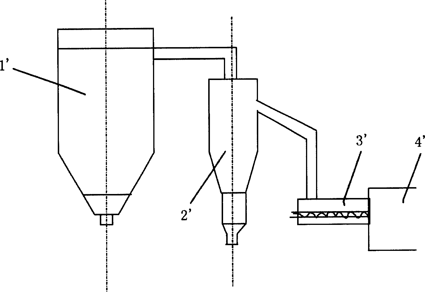
[0021] Please refer to figure 2 As shown, the lead powder machine 100 of the present invention includes a powder collector 1, a cyclone separator 2 connected to the powder collector 1 through a pipeline (not labeled), a drum 4 and a hollow shaft 3 connected to the drum 4, the hollow shaft 3 There are at least two powder returning screws 31 inside, and the hollow shaft 3 is connected with the cyclone separator 2 through a pipeline 20 . The powder collector 1, the cyclone separator 2 and the drum 4 of the lead powder machine 100 of the present invention are the same as those of the prior art, and will not be described here. Only the differences between the present invention and the prior art will be described in detail below.

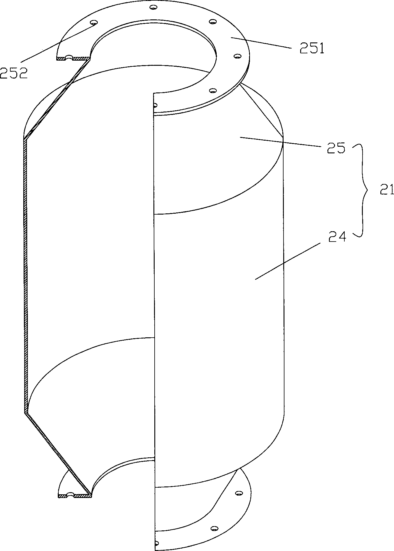
[0022] Please refer to figure 2 , image 3 As shown, the pipe 20 includes an upright pipe 21 and an inclined pipe 22 , and the upright pipe 21 includes a thickened portion 24 and necks 25 respectively connected to the upper and lower ends of the thick...


PUM

PropertyMeasurementUnit
heightaaaaaaaaaa
heightaaaaaaaaaa
diameteraaaaaaaaaa

Abstract

A lead powder machine is composed of powder collector, cyclone separator, hollow axle, the pipeline connected between cyclone separator and hollow axle and with a thickened segment, and drum. In said hollow axle there are three powder returning screws for returning the big particles back into drum to grind again.

Description

technical field [0001] The invention relates to a lead powder machine, in particular to a lead powder machine which can reduce the apparent specific gravity of the lead powder without reducing the output of the lead powder. Background technique [0002] The working principle of the lead powder machine is that the lead ball is input into the lead powder machine for grinding, and oxidized into fine powder at a certain temperature, and then the lead powder is taken out by the draft and blast air flow and enters the powder collector for collection. The impact collision and friction grinding of the lead ball in the drum of the lead powder machine, on the one hand, accelerates the shedding speed of the lead oxide (PbO) layer on the surface of the lead ball, and on the other hand, the heat generated accelerates the lead oxidation reaction speed, so the lead powder machine in the working process , as the load in the cylinder gradually increases, the heat generated gradually increase...

Claims


Application Information

Patent Timeline
Patent Type & Authority Applications(China)
IPC IPC(8): B22F9/04
Inventor 赵恒祥
Owner 赵恒祥
Why Eureka
Try Eureka