Thin wall mould component

A formwork component and thin-wall technology, which is applied to building components, building structures, floor slabs, etc., can solve problems affecting the overall quality and mechanical performance of cast-in-place concrete hollow floors, inconsistent thickness of concrete protective layers, and layout of formwork components. Inconvenience and other problems, to achieve the effect of reducing the amount of steel bars and concrete, reducing construction costs, and simple structure

Inactive Publication Date: 2006-06-28
湖南邱则有专利战略策划有限公司
View PDF4 Cites 0 Cited by
  • Summary
  • Abstract
  • Description
  • Claims
  • Application Information

AI Technical Summary

Problems solved by technology

However, after being applied to dense ribbed floors, the formed dense ribs are all rectangular dense ribs, and their mechanical performance is not very reasonable. It is often necessary to increase the cross-sectional size of the dense ribs, increase the amount of steel bars and concrete, and increase the cost of the floor. At the same time, the layout of the formwork components is inconvenient, and the phenomenon of inconsistency in the width of the cast-in-place concrete ribs and the inconsistency of the thickness of the concrete protective layer between the formwork components is prone to occur, thereby affecting the overall quality and mechanical performance of the cast-in-place concrete hollow floor, increasing Construction difficulty, therefore, the development of a new type of thin-walled formwork components has been urgently needed

Method used


Image

  • Thin wall mould component
  • Thin wall mould component
  • Thin wall mould component

Examples


Embodiment Construction

[0048] The present invention will be further described below in conjunction with the accompanying drawings and embodiments.

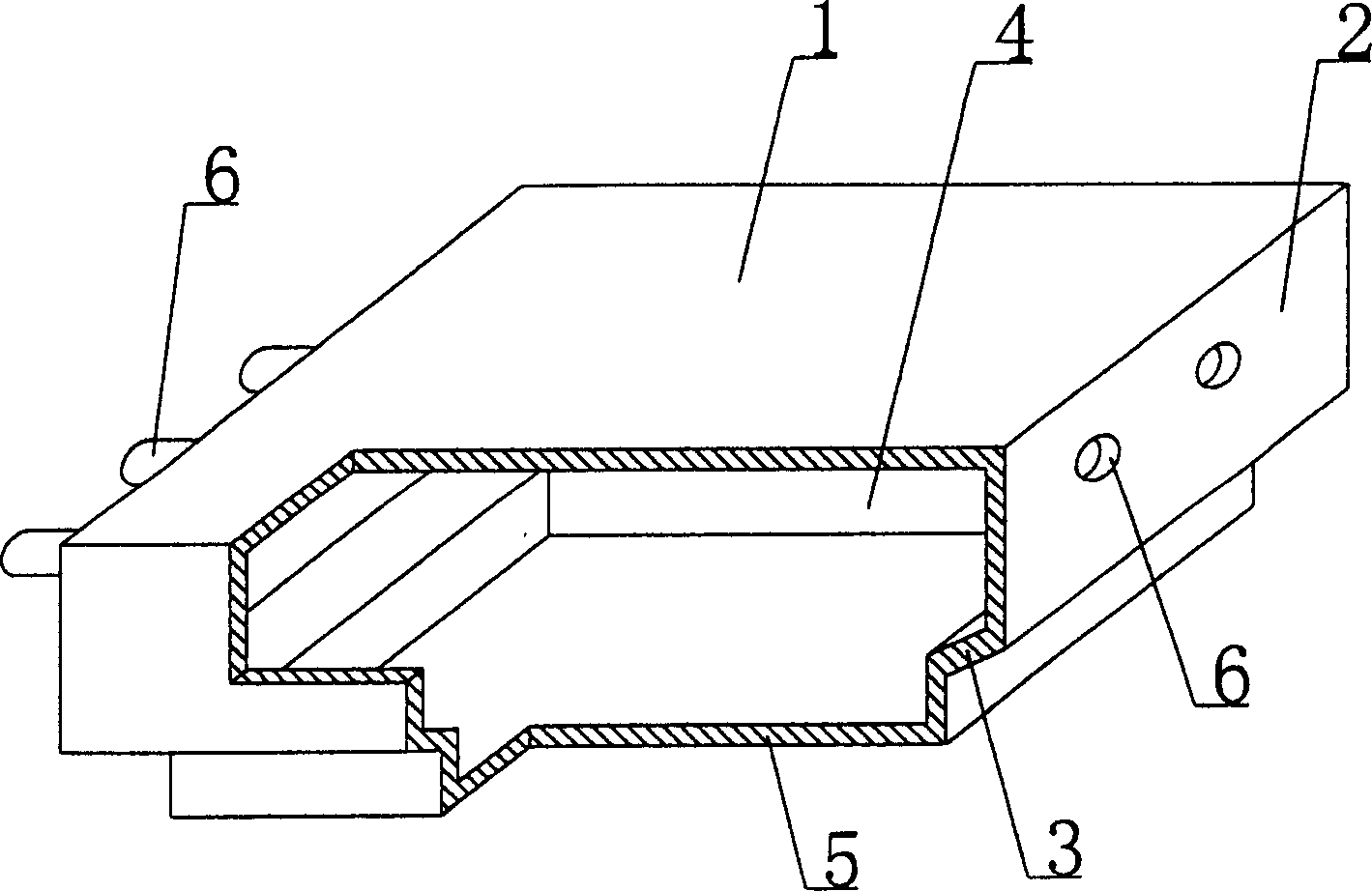
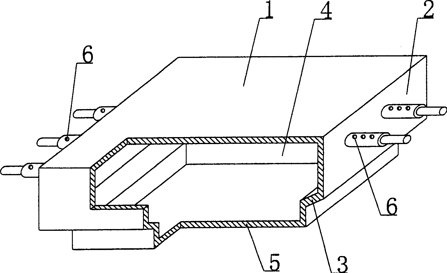
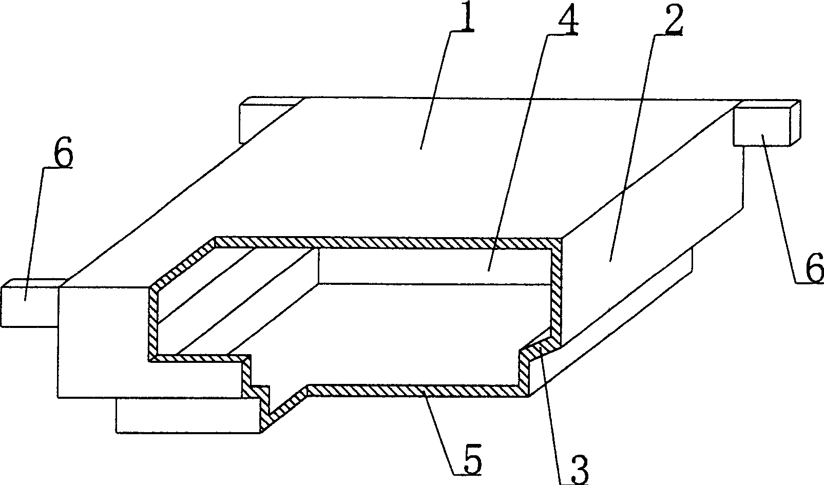
[0049] As shown in the accompanying drawings, the present invention includes an upper plate 1, surrounding side walls 2, and a lower bottom 3, and the upper plate 1, surrounding side walls 2, and lower bottom 3 form a cavity 4, which is characterized in that there is at least one on the lower bottom 3 The boss module 5 that protrudes from the lower bottom 3 is provided with at least one connecting part 6 on at least one pair of opposite surrounding side walls 2. The connecting part 6 protrudes laterally from the upper plate 1, and at least one pair of opposite connecting parts 6 are on the same side. on-line. figure 1 It is a structural schematic diagram of Embodiment 1 of the present invention. In the accompanying drawings, 1 is the upper plate, 2 is the surrounding side wall, 3 is the lower bottom, 4 is the cavity, 5 is the boss module, 6 is the conn...


PUM


Abstract

The invention is a thin wall mold shell component, comprising top plate, side walls and bottom plate, which compose a cavity and characterized in that the bottom plate is provided with at least a boss module protruded from it, at least a pair of opposite side walls is provided with at least a pair of opposite connection parts, which transversely extend from the top plate, and at least a pair of opposite connection parts is in the same line. It is applied to hollow building covers, house covers, walls, foundation slabs and hollow bridge beams of cast-in-site reinforced concrete or prestressed reinforced concrete, especially beamless building covers.

Description

[0001] This application is a divisional application of an invention patent application with the filing date of June 30, 2003, the application number of 03145630.8, and the title of "a thin-walled formwork component". (1) Technical field [0002] The present invention relates to a thin-walled formwork member. (2) Background technology [0003] At present, the cast-in-place concrete hollow floor is a widely used floor structure. The lightweight permanent tire molds filled in it include various hollow tubes and boxes, and the boxes are hollow or solid. For example, the patent No. ZL99249798.1, which the applicant applied for on November 29, 1999, is a utility model patent named "fiber-reinforced thin-walled member for reinforced concrete filling", which discloses a thin-walled formwork member, including an upper plate, The surrounding side walls, the lower bottom, and the upper plate, the surrounding side walls and the lower bottom form a polyhedral cavity. Another example is ...

Claims


Application Information

Patent Timeline
Patent Type & Authority Applications(China)
IPC IPC(8): E04B5/36E04B5/19
Inventor 邱则有
Owner 湖南邱则有专利战略策划有限公司
Why Eureka
Try Eureka