Bending resonance type magnetoelectric composite material and its manufacturing method

A technology of magnetoelectric composite materials and piezoelectric composite materials, which is applied in the selection of device materials and the manufacture/assembly of magnetostrictive devices, which can solve the problems of high operating frequency, unfavorable device miniaturization, and large loss.

Inactive Publication Date: 2006-06-28
NANJING UNIV
View PDF1 Cites 11 Cited by
  • Summary
  • Abstract
  • Description
  • Claims
  • Application Information

AI Technical Summary

Problems solved by technology

Although the magnetoelectric effect of these magnetoelectric composite structures has been greatly improved, their operating frequency is relatively high, which causes a large loss of energy in the process of magnetoelectric coupling, thereby reducing the energy conversion efficiency of magnetoelectric coupling.
For this reason, it is necessary to reduce its resonance frequency, but this will inevitably lead to an increase in the structure size of the magnetoelectric composite material, which is not conducive to the miniaturization of the device and increases the manufacturing cost

Method used


Image

  • Bending resonance type magnetoelectric composite material and its manufacturing method
  • Bending resonance type magnetoelectric composite material and its manufacturing method
  • Bending resonance type magnetoelectric composite material and its manufacturing method

Examples


Embodiment 1

[0021] Embodiment 1. Magnetoelectric composite material of the present invention

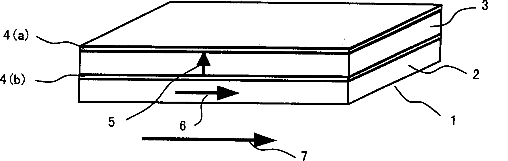
[0022] Such as figure 1 As shown, the magnetoelectric composite rectangular sheet 1 is formed by laminating a TbDyFe alloy rectangular sheet 2 with magnetostrictive effect and a PZT piezoelectric ceramic rectangular sheet 3 with piezoelectric effect. Wherein, there are planar electrodes 4 (a) and 4 (b) for output voltage on the surface of the PZT piezoelectric ceramic rectangular sheet 3, and the polarization direction of the PZT piezoelectric ceramic rectangular sheet 3 is along the thickness direction, such as figure 1 Indicated by the middle arrow 5; in the TbDyFe alloy rectangular sheet 2, the magnetic domain has a preferred orientation along the length direction, such as figure 1 Shown by middle arrow 6.

[0023] The overall size of the magnetoelectric composite rectangular sheet 1 is: 18.0 mm (length) × 5.0 mm (width) × 1.6 mm (thickness), wherein the dimensions of the TbDyFe alloy recta...

Embodiment 2

[0032] Embodiment 2. The magnetoelectric composite material of the present invention.

[0033] The structure and size of the magnetoelectric composite material of this embodiment are all the same as those of the magnetoelectric composite material of Example 1, and it is a rectangular sheet as a whole, consisting of a magnetostrictive material rectangular sheet and a piezoelectric material rectangular sheet combined. The basic difference between the magnetoelectric composite material of this embodiment and the magnetoelectric composite material of Embodiment 1 is that: the magnetostrictive material in this embodiment is Terfenol-D / epoxy resin composite material, and the piezoelectric material is PZT / ring Oxygen composite material. Other aspects, such as the electrode arrangement and polarization direction of the piezoelectric material, and the magnetic domain orientation of the magnetostrictive material, are the same as those of the magnetoelectric composite material in Exampl...

Embodiment 3

[0045] Embodiment 3. The magnetoelectric composite material of the present invention.

[0046] The structure and components of the magnetoelectric composite rectangular sheet of the present embodiment are all the same as those of the magnetoelectric composite rectangular sheet of Example 1, the magnetostrictive layer is made of Terfenol-D rectangular sheet, and the piezoelectric layer is made of Pb(Zr 0.52 Ti 0.48 )O 3 (PZT) rectangular sheet configuration. The basic difference between the magnetoelectric composite material of this embodiment and the magnetoelectric composite material of Embodiment 1 is that: in this embodiment, the size of the rectangular piece of magnetoelectric composite material has changed, and the overall size is 25.0mm (length) × 5.0 mm (width)×2.0 mm (thickness), wherein the dimensions of the Terfenol-D rectangular sheet and the PZT rectangular sheet are both 25.0×5.0×1.0 mm. Other aspects, such as the electrode arrangement and polarization directi...


PUM


Abstract

An electromagnetic compound material is formed by laminating a rectangular plate of magnetostrictive material and rectangular plates of piezoelectric materials in a same shape having a pair of plane electrodes and being polarized along the thickness direction, in which, the electromagnetic compound rectangular plate is applied with an AC magnetic field and a DC bias magnetic field along the length direction, when the frequency of the AC magnetic field equals to a stage curved resonance frequency of the electromagnetic complex material rectangular plate, the plate will generate bend resonance and the piezoelectric layer will output voltages to realize the transformation from magnetic energy to electric energy, when the applied DC bias magnetic field strength is suitable, the voltage output by the piezoelectric layer reaches to the maximum and the energy conversion efficiency is the maximum.

Description

technical field [0001] The invention relates to a magnetoelectric composite material composed of a piezoelectric material and a magnetostrictive material working in the first-order bending resonance coupling mode. Background technique [0002] Magnetoelectric materials are a class of materials with magnetoelectric effects. On the one hand, they can produce dielectric polarization under the action of a magnetic field. On the other hand, they can also be magnetized under the action of an electric field. The field of transducers such as electric energy conversion has potential application value. The magnetoelectric voltage coefficient is an important index to characterize the magnetoelectric effect of materials, which is defined as α E =dE / dH, where E is the electric field output of the material and H is the applied external magnetic field. There are two major categories of known magnetoelectric materials, including single-phase compounds and composite materials. Among them,...

Claims


Application Information

Patent Timeline
Patent Type & Authority Applications(China)
IPC IPC(8): H01L41/16H01L41/47
Inventor 万建国刘俊明王广厚
Owner NANJING UNIV
Why Eureka
Try Eureka