
Projecting unit

A projection device and projection screen technology, applied in projection devices, optics, instruments, etc., can solve the problems of complex, expensive and wasteful projection devices.

Inactive Publication Date: 2006-07-05
林志雄
View PDF2 Cites 1 Cited by
  • Summary
  • Abstract
  • Description
  • Claims
  • Application Information

AI Technical Summary

Problems solved by technology

[0004] Existing projection devices are relatively complex and expensive, and it would be a waste if they are only used to project simple images such as text, patterns, and digital symbols.

Method used


Image

  • Projecting unit
  • Projecting unit
  • Projecting unit

Examples


Embodiment Construction

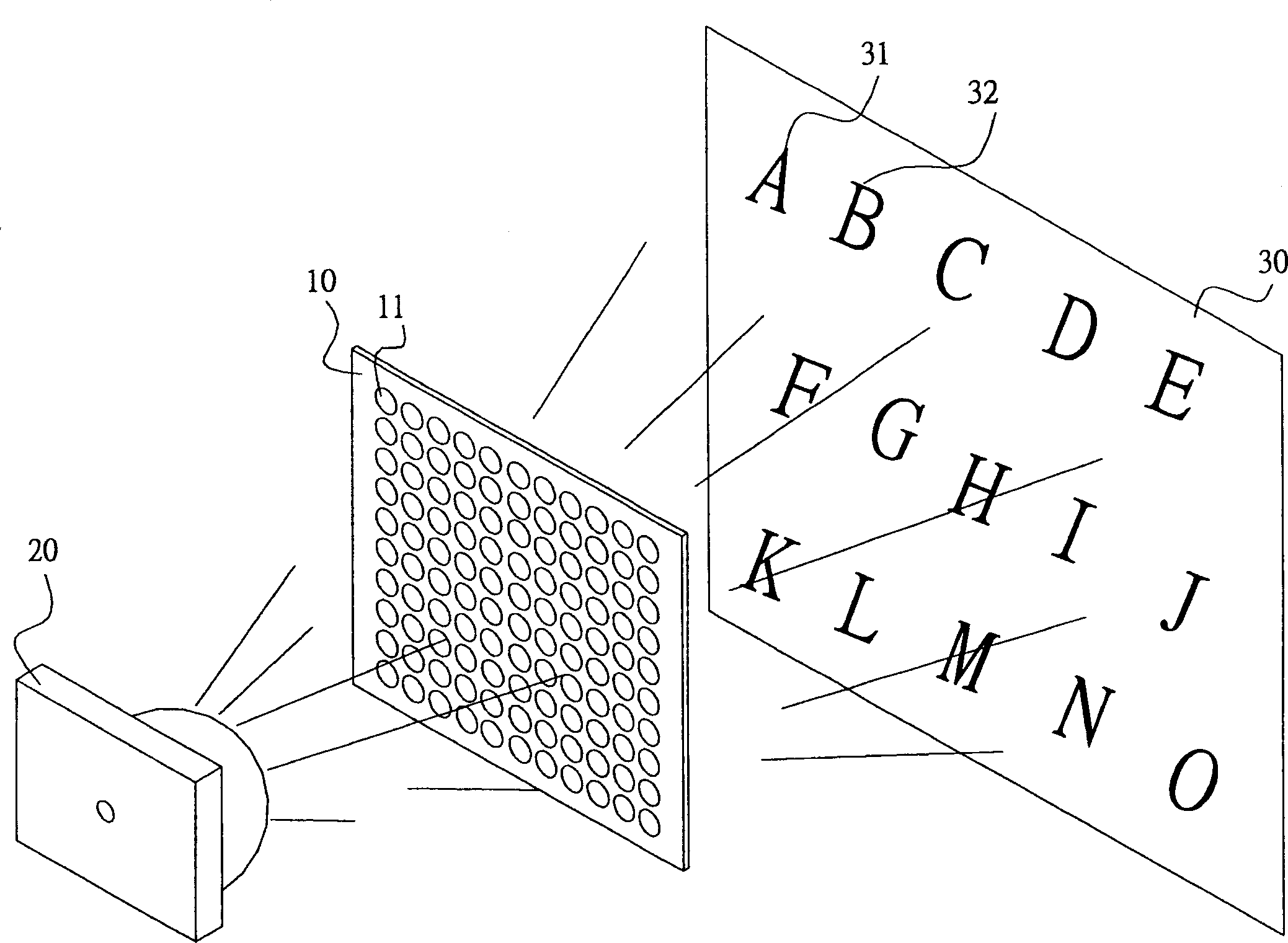
[0020] see figure 1 shown. The first embodiment of the projection device of the present invention mainly includes a lens body 10, which can be made of transparent materials such as glass, acrylic, and plastic. The lens body 10 is in the shape of a sheet and has a plurality of lens units 11 . The plurality of lens units 11 can be arranged in an array. A plurality of lens units 11 are divided into several groups, and each group of lens units 10 has a different light projection angle, which can respectively focus the light emitted by the light source body 20 and change the traveling direction of the light, and project it on the projection screen 30 for direct collection. Multiple light spots display images. As in this embodiment, a plurality of light spots projected through the lens body 10 are collected respectively to display images 31 , 32 such as “A” and “B” of relatively bright English characters.

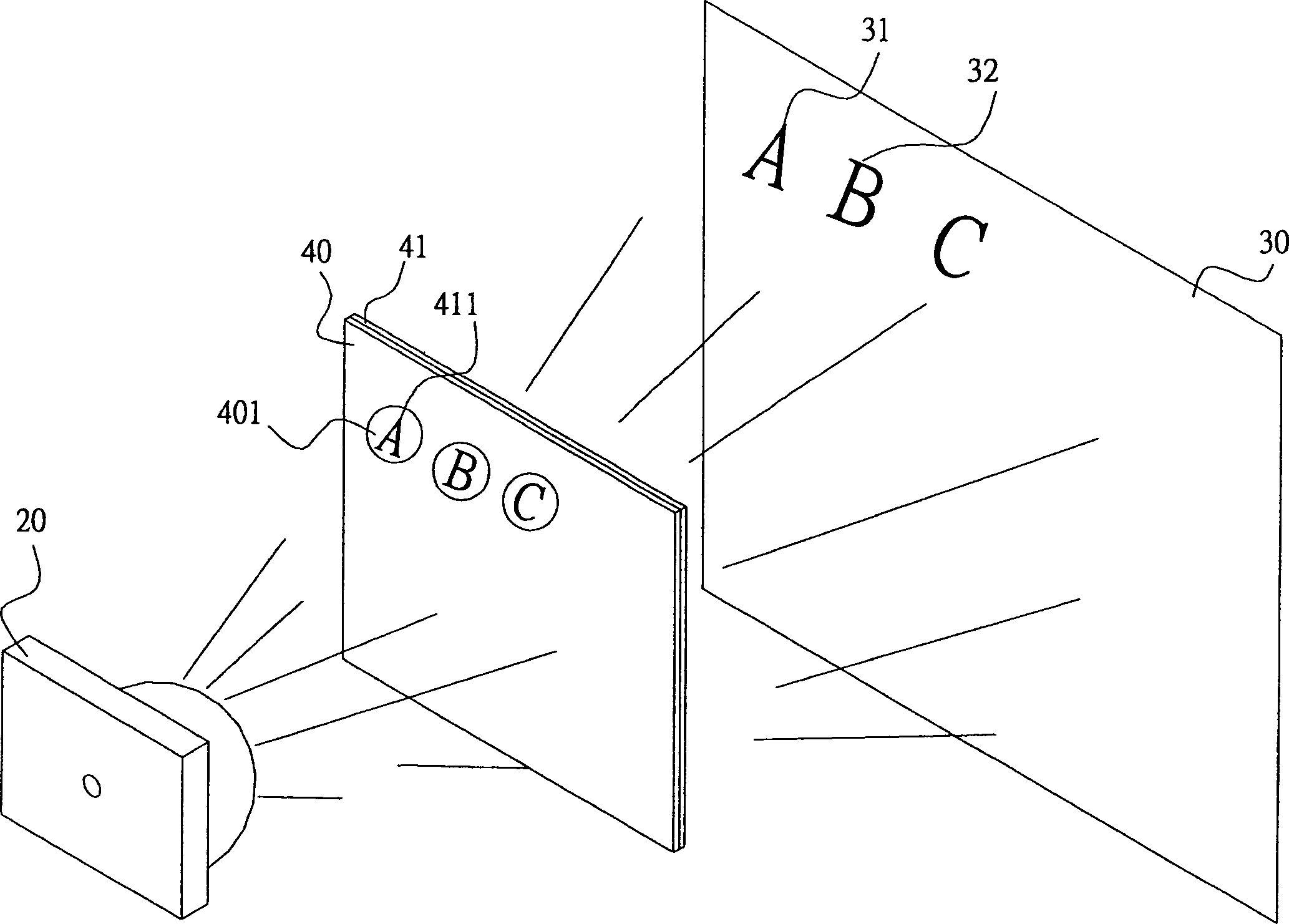
[0021] The lens body of this embodiment can also make the light projecte...


PUM


Abstract

The invention is a projector, comprising a lens main body having plural lens units, each of which has a shape for making a light projected at a specified angle, respectively focusing the lights irradiating the main body and changing their advancing directions to make them projected on a projection screen, and directly collecting the light spots of these lens units to compose the set brighter video; or collecting plural light spots to compose a brighter background so as to display the set darker reverse video in the brighter background; or projecting the amplified videos of video units corresponding to the lens units. The invention is simple in structure and easy to manufacture.

Description

technical field [0001] The present invention relates to a projection device, especially a projection device that projects an image using a lens with a plurality of projection units. Background technique [0002] A general projection device, such as the projector disclosed in Taiwan Invention Patent No. 222549 published on October 21, 2004, includes a light bulb (Lamp) for emitting a light; an optical engine for receiving the light and outputting A picture is projected onto a screen outside the projector. [0003] General projection devices often use an array of lenses to condense light or change the direction of light. For example, the Chinese Taiwan New Patent No. 245445 published on October 1, 2004 discloses an image display device and a projector with a lens array unit. The partial lights for dividing the illumination light into many parts are collected separately. Another example is the Chinese Taiwan Invention Patent Announcement No. 594372 published on June 21, 2004,...

Claims


Application Information

Patent Timeline
Patent Type & Authority Applications(China)
IPC IPC(8): G03B21/14G03B21/00
Inventor 林志雄
Owner 林志雄
Learn More