Mechanical type tilting motion switch

A mechanical and switch technology, applied in the direction of electric switches, electrical components, circuits, etc., can solve the problems of high cost, unsuitable safety control of gas cookers, and difficult processing and manufacturing

Inactive Publication Date: 2006-07-05
HUNAN XUNDA JI TUAN YOU XIAN GONG SI
View PDF3 Cites 9 Cited by
  • Summary
  • Abstract
  • Description
  • Claims
  • Application Information

AI Technical Summary

Problems solved by technology

In addition, the tilting transmitter disclosed in Chinese patent application No. 98117787.5, and the sensing device disclosed in Chinese patent application No. 01142166.5, which has no installation direction restriction and can reset automatically, all belong to mechanical control switches, and they are all installed in the equi

Method used


Image

  • Mechanical type tilting motion switch
  • Mechanical type tilting motion switch
  • Mechanical type tilting motion switch

Examples


Embodiment Construction

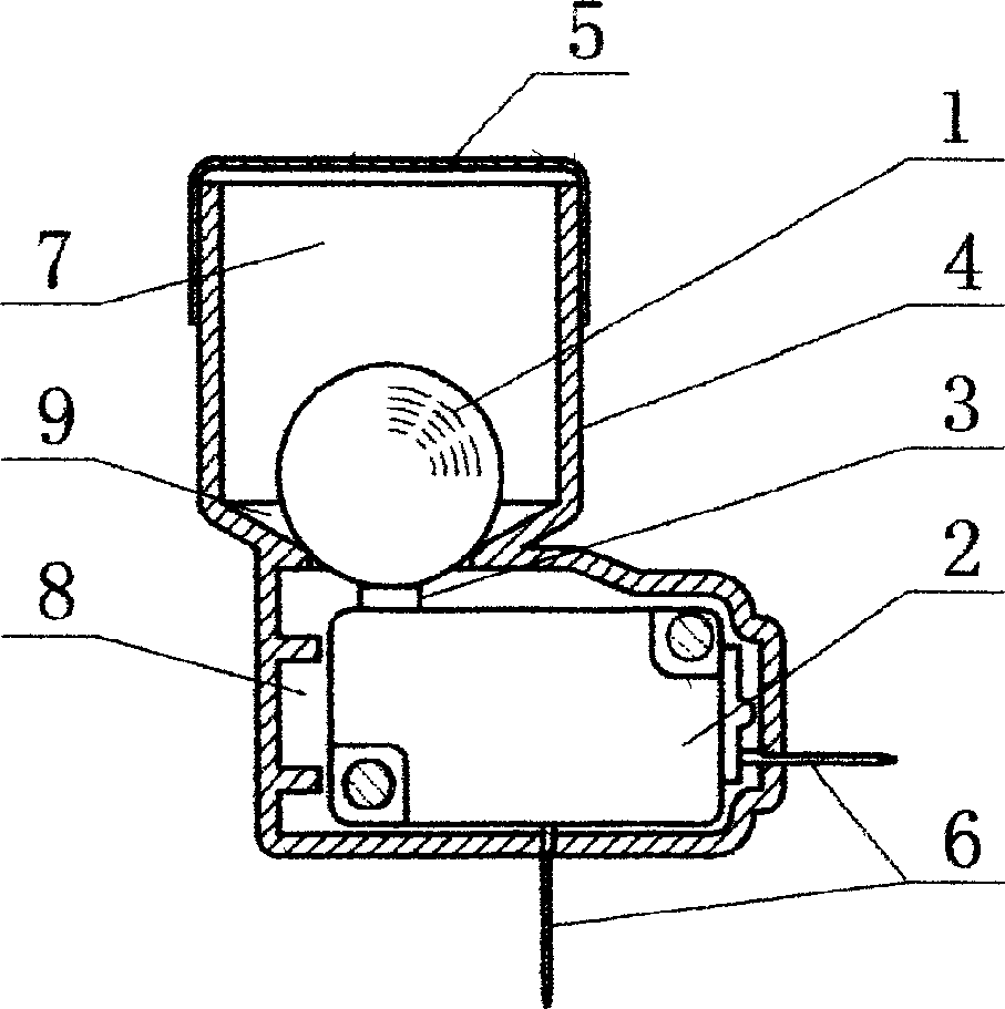
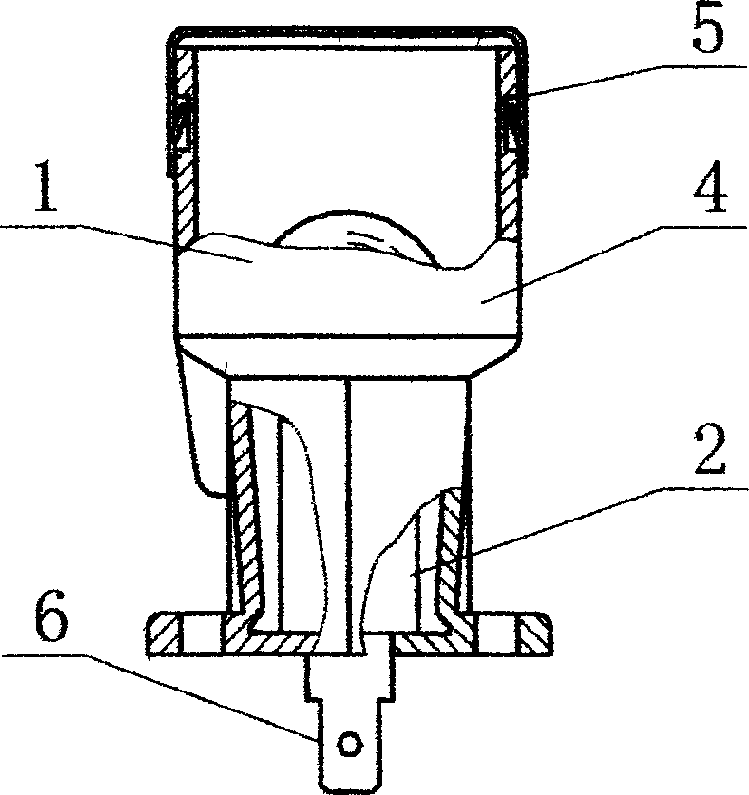
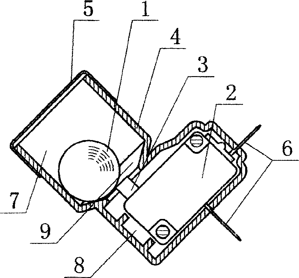
[0009] The following is a further detailed description of the mechanical dump switch in conjunction with the accompanying drawings:

[0010] The main function of the heavy ball 1 of the mechanical dump switch is to press the switch contact rod 3 of the micro switch 2 when the burner is vertical, and press it into the micro switch 2, and the micro switch 2 is in the power-on state. state, when the burner deviates from the vertical position and tilts, the heavy ball 1 will roll to the center position because the wall of the conical cavity 9 is an oblique cone, and the heavy ball 1 will be out of contact with the switch contact rod 3, and the switch contact rod 3 will pop out and reset , the micro switch 2 is in the electrical off state. Heavy Ball 1 uses steel balls.

[0011] The mechanical dump switch is equipped with a heavy ball 1 and a micro switch 2 in the housing 4 . The inner cavity of the housing 4 is divided into an upper cavity 7 , a conical cavity 9 and a lower cavi...


PUM


Abstract

The switch is composed of body case, micro switch and heavy ball. There is upper cavity, conic cavity and lower cavity connected in the body case. Passing through body case, electric lug plate of the micro switch is extended out of the body case. Position of the bunter of the micro switch is faced to the conic cavity. An upper cover seals cavity mouth. The disclosed switch can turn off circuit in any oblique direction in 360 degrees. Features are: simple structure, stable operation.

Description

technical field [0001] This invention relates to a switch operated by a change of physical state, and more particularly to a mechanical tipping switch. Background technique [0002] For movable gas appliances, if they are placed unreasonably, when they are used at a certain angle, it will affect the normal working conditions of the gas appliances, resulting in unstable combustion, increasing the carbon monoxide content in the combustion exhaust gas, and other abnormal working conditions. cause safety accidents. In order to prevent such adverse phenomena caused by tilting gas appliances, some gas appliances are equipped with anti-dumping switches. When the gas appliances are tilted to a certain angle, the gas valves are controlled to close to protect the gas appliances. At present, most of these switches use mercury switches, which are expensive and extremely unsafe. Mercury can easily cause environmental pollution and make operators prone to mercury poisoning. A large numbe...

Claims


Application Information

Patent Timeline
IPC IPC(8): H01H35/02
Inventor 麦青伍斌强
Owner HUNAN XUNDA JI TUAN YOU XIAN GONG SI
Why Eureka
Try Eureka