Triangle mechanism for needle selection of flat knitting machine

A technology of flat knitting machine and cam, applied in the direction of weft knitting, knitting, textile and paper making, etc., can solve the problems of high manufacturing cost, poor working reliability, occupying space, etc., and achieve high transmission reliability and motion precision, needle selection The effect of simplifying and reducing the manufacturing cost by using the triangular mechanism

Inactive Publication Date: 2006-07-12
冯加林
View PDF0 Cites 9 Cited by
  • Summary
  • Abstract
  • Description
  • Claims
  • Application Information

AI Technical Summary

Problems solved by technology

However, this linkage mechanism is relatively complicated, and there are about 90 components, which occupy most of the space behind the triangular bottom plate, and the manufacturing cost is high. The manufacturing cost of each linkage mechanism is at least five hundred yuan, and the transmission is through The magnetic steel absorbs the needle bed, which is realized by moving relative to the machine head, the work reliability is poor, and the movement accuracy is not high

Method used


Image

  • Triangle mechanism for needle selection of flat knitting machine
  • Triangle mechanism for needle selection of flat knitting machine
  • Triangle mechanism for needle selection of flat knitting machine

Examples


Embodiment 1

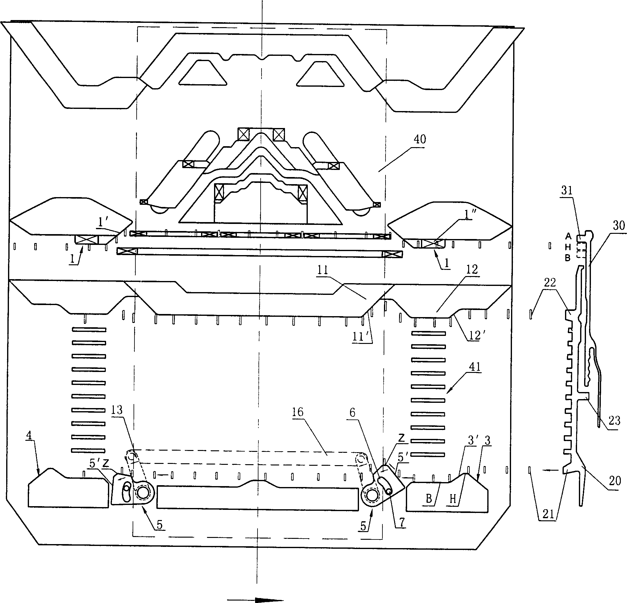
[0025] See figure 1 , the two selector movable needle cams 3 and 4 on the lower side of the knitting system are hinged to the triangular bottom plate 10 through the pivot pin 18, and the rear side of the cam bottom plate 10 corresponds to the pivot pin The position place is connected with the pendulum piece 13 of a rotating shaft altogether. The movable needle-starting triangles 5 of the two selectors are placed according to a certain positional relationship: if the needle-setting triangle 5 of the right selector is inclined, the needle-raising triangle 5 of the left selector is almost flat. The high end Z of the bevel 5' is slightly higher than the left selector jack triangle 4; and vice versa. The two selector jacks that are placed according to the above-mentioned positional relationship are respectively hinged to the two ends of a connecting rod 16 through the pendulum piece 13 that is connected with the same rotating shaft. A limit hole 6 is provided on the movable need...

Embodiment 2

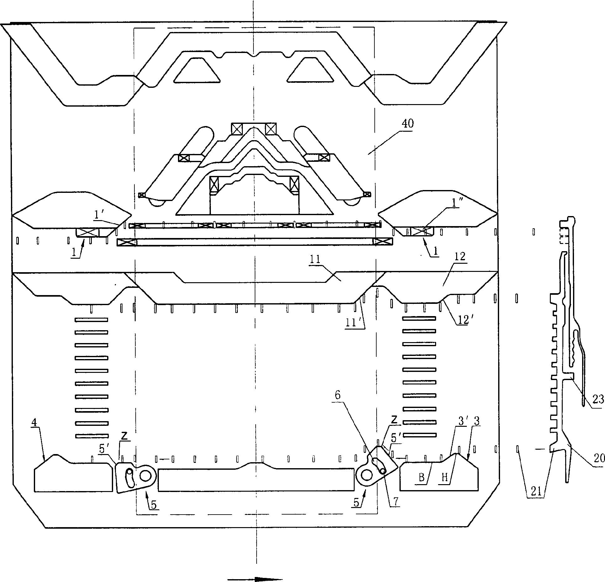
[0030] See image 3 , This embodiment is basically the same as the above-mentioned embodiment, except that a tension spring 8 is placed on the connecting rod 16 and placed in a groove of the connecting rod 16 . Like embodiment 2, the connecting rod 16 is also placed on the rear side of the triangular bottom plate, and is connected with the connecting rod 16 through the pendulum piece 13 which is connected with the movable needle raising cam 5 of the selector and placed on the rear side of the triangular bottom plate. Please refer to Figure 4 , the selector movable needle triangle 5 and the pendulum piece 13 have a total rotating shaft. A connecting pin 14 is provided on the pendulum piece 13, and a waist-shaped hole 17 is respectively provided at both ends of the connecting rod 16, and the connecting rod 16 slides with the connecting pins 14 on the two pendulum pieces through the waist-shaped hole 17. The arc length (or the included angle) of the limit hole 6 on the needle o...

Embodiment 3

[0034] See Figure 5 , The mechanism side in the present embodiment is simpler, and the function of the connecting rod 16 is replaced by the return spring-extension spring 18. One end of extension spring 18 is connected on the triangular bottom plate 10, and one end is connected with two needle selector movable needle cams 5 .

[0035] The needle movement process of the butts of the selector jack 20 and the pattern piece 30 in this embodiment is also exactly the same as that of Embodiment 1, except that the rear butt 21 on the selector jack 20 starts to move when entering the left selector jack. In the area of ​​the needle cam 5, the movable needle cam 5 of the needle selector has a hindering effect on the rear needle butt 21, and the rear needle butt 21 acts on the movable needle cam 5 of the needle selector, so that it rotates counterclockwise to the horizontal position, There is no hindrance to the left movement of the needle butt 21 and a passage for the rear needle butt ...


PUM


Abstract

The invention relates to a horizontal-woven device, which provides a triangle device for selecting needle of horizontal-woven device. The knitting system comprises two needle-selection plate movable triangles; two flower-types recover triangles and a triangle bottom plate. Wherein, said needle-selection movable triangles are symmetry hinged on the triangle bottom plate which can rotate around the hinge point; and said flower-type recover triangle is fixed on the triangle bottom plate with an operation inclined surface on it. The invention comprises the advantages that: using rotational needle-selection triangle and fixed type and flower-type recover triangle to simplify the needle-selection triangle device, therefore, the whole device needs tens of elements with smaller volume, reduced producing cost, improved transmission reliability and motion accuracy.

Description

technical field [0001] The invention relates to a flat knitting machine, in particular to a cam mechanism for needle selection of a flat knitting machine. Background technique [0002] In the knitting of each row of the flat knitting machine, there are four knitting states: knitting, tucking, transfer and non-knitting. All kinds of knitting patterns of flat knitting machine knitting fabrics are realized by any combination of the above four knitting states of knitting needles. The knitting state of the knitting needle is determined by the position of the pattern sheet in the needle groove. Generally, the pattern sheet has three positions of B, H, and A in the needle groove from low to high. Which position is mainly determined by It is controlled by the selector start triangle and the selector reset triangle. The inclined plane of the needle selection cam pushes against the rear heel of the selector to move the selector up, and then the lower heel of the selector pushes the ...

Claims


Application Information

Patent Timeline
Patent Type & Authority Applications(China)
IPC IPC(8): D04B15/82
Inventor 冯加林巫友群
Owner 冯加林
Why Eureka
Try Eureka