
Pulsating stepless transmission

A technology of continuously variable transmission and rotary motion, applied in the direction of transmission, gear transmission, belt/chain/gear, etc., can solve the problem of large pulsation, complex structure of pulsating continuously variable transmission, load capacity of one-way overrunning clutch and impact resistance Capability limitations and other issues, to achieve stable performance, improved reliability, stable and accurate output

Inactive Publication Date: 2006-07-12
吴华峰
View PDF2 Cites 2 Cited by
  • Summary
  • Abstract
  • Description
  • Claims
  • Application Information

AI Technical Summary

Problems solved by technology

[0003] The disadvantage of the traditional pulsating continuously variable transmission is limited by the carrying capacity and impact resistance of the one-way overrunning clutch, the output mechanism has become a fatal flaw of the traditional pulsating continuously variable transmission, so it can only be applied to low-speed, medium and small power
Moreover, the one-way overrunning clutch can only output the power of the transmission mechanism with the largest instantaneous angular velocity, and the pulsation is relatively large. The method of increasing the number of phases of the combination mechanism to reduce the pulsation will also make the structure of the pulsation continuously variable transmission more complicated.

Method used


Image

  • Pulsating stepless transmission
  • Pulsating stepless transmission
  • Pulsating stepless transmission

Examples


Embodiment Construction

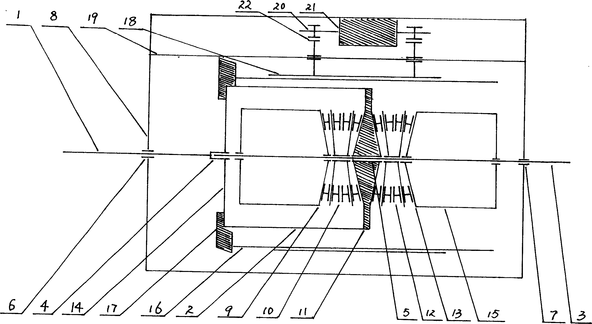
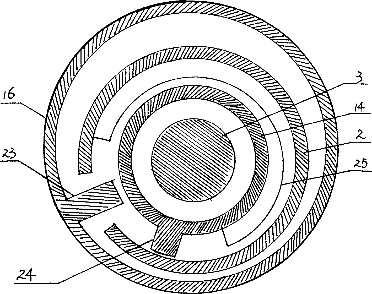
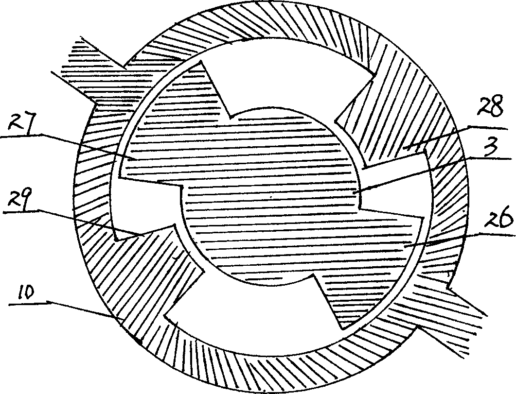
[0014] figure 1 The schematic diagram of the pulsating continuously variable transmission provided by the present invention is shown. The input shaft (1) of the pulsating continuously variable transmission and the input shaft cylinder (2) integrated with the input shaft and the output shaft (3) are concentric with each other and can pass through The bearing (4) and the bearing (5) support each other, the input shaft is supported on the housing (8) through the bearing (6), and the output shaft is supported on the housing (8) through the bearing (7). (9), (11) are the two conical center wheels of the 2Z-X type positive sign mechanism bevel gear differential train with a transmission ratio of 1:1, (10) are the rotating arms of the differential train, two conical Center wheel (11), (13) and rotating arm (12) constitute another bevel gear differential train. The two bevel gear differential trains share a center wheel (11), and the center wheel (11) is integrated with the input sha...


PUM


Abstract

The invention relates to a impulse non-stepped speed changer, wherein, one end of transmission is connected to the input axle, and another end is connected to the input axle to seal two central wheels of 2Z-X type positive taper gear differential wheel system whose closed transmission rate is 1:1; it uses rotational arm to output power and stepped output the power via two combined devices with 180 degree phase difference. The invention has overcome the defect the of traditional impulse non-stepped speed changer, with reasonable structure, simple control, high economic benefit, high loading ability, wider speed change rage, stable output torque, and the application for high-speed large power vehicle speed change system.

Description

technical field [0001] The invention relates to a mechanical continuously variable transmission, in particular to a pulse continuously variable transmission. Background technique [0002] As we all know, the traditional pulsating continuously variable transmission uses a transmission mechanism to convert the uniform rotational motion of the transmission main shaft into a variable speed rotational motion applied to the one-way overrunning clutch, and then convert it into a one-way pulsating rotational motion of the output shaft through the one-way overrunning clutch; Through several combined mechanisms with a certain phase difference, the output shaft obtains unidirectional rotary motion with small pulse amplitude. Use the speed regulating mechanism to change the length of a certain component in the transmission mechanism or change the eccentricity of a certain component to form a new size proportional relationship between the components, thereby changing the angular velocity...

Claims


Application Information

Patent Timeline
Patent Type & Authority Applications(China)
IPC IPC(8): F16H37/02
CPCF16H3/76
Inventor 吴华峰
Owner 吴华峰
Learn More