Lamp feeding system and lamp thereof

一种馈电系统、馈电线的技术,应用在馈电系统领域,能够解决灯减少使用寿命、断落、环境加重负担等问题,达到热力负荷减小的效果

Inactive Publication Date: 2006-07-12
PATENT TREUHAND GESELLSCHAFT FUER ELECTRIC GLUEHLAMPEN M B H
View PDF1 Cites 0 Cited by
  • Summary
  • Abstract
  • Description
  • Claims
  • Application Information

AI Technical Summary

Problems solved by technology

The disadvantage of this feed system is that, on the one hand, the effective sealing length of the molybdenum foil is reduced due to the insufficient sealing effect in the chrome-plated area and thus the sealing effect of the neck seal reduces the service life of the lamp. On the other hand, the cladding process is not only burdensome to the environment, but also excessively expensive and costly due to the largely manual production method
Another disadvantage is that the outer feeder wires may easily fall out of the shut-off seal interruption due to axial tension

Method used


Image

  • Lamp feeding system and lamp thereof
  • Lamp feeding system and lamp thereof

Examples


Embodiment Construction

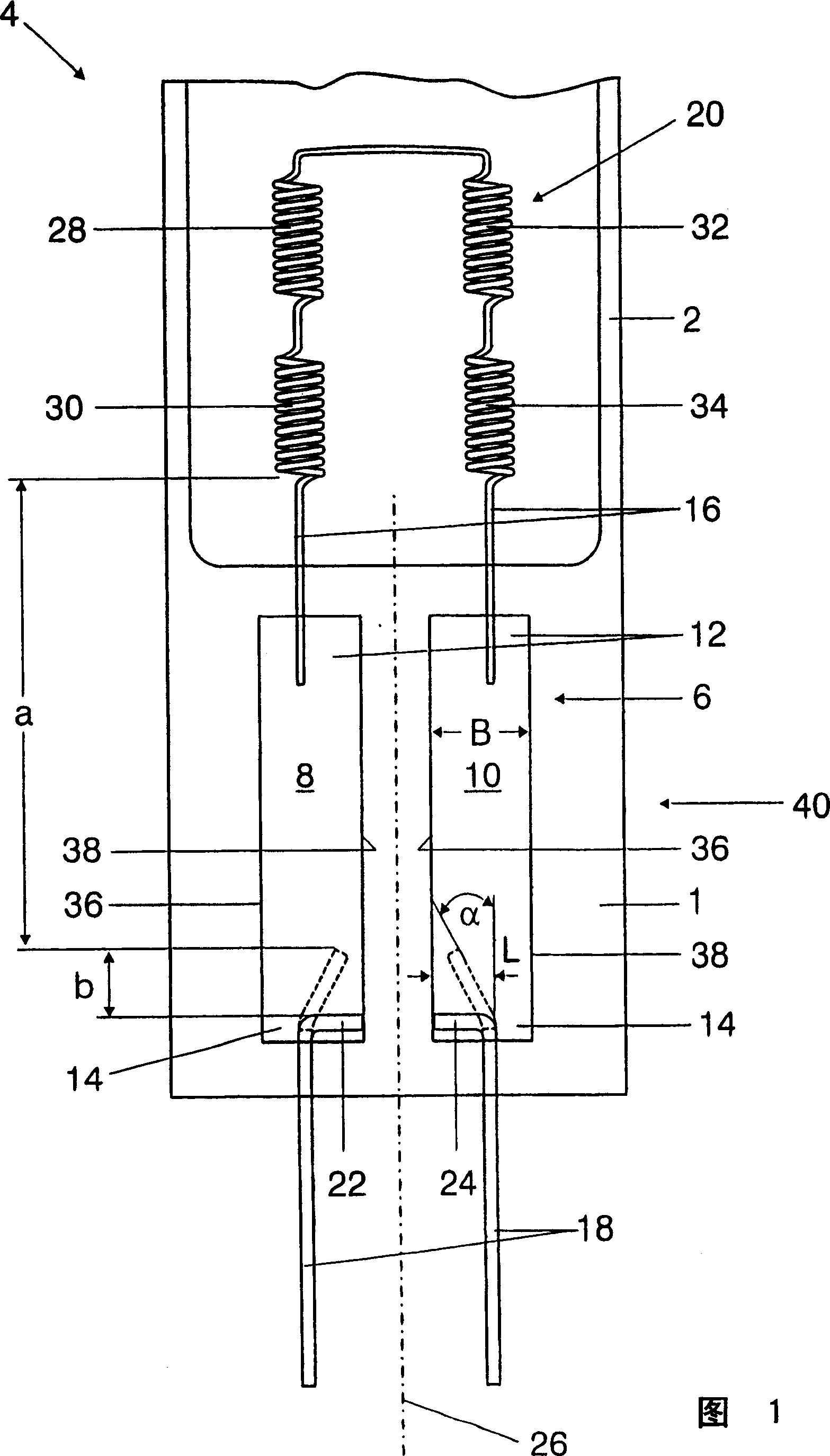
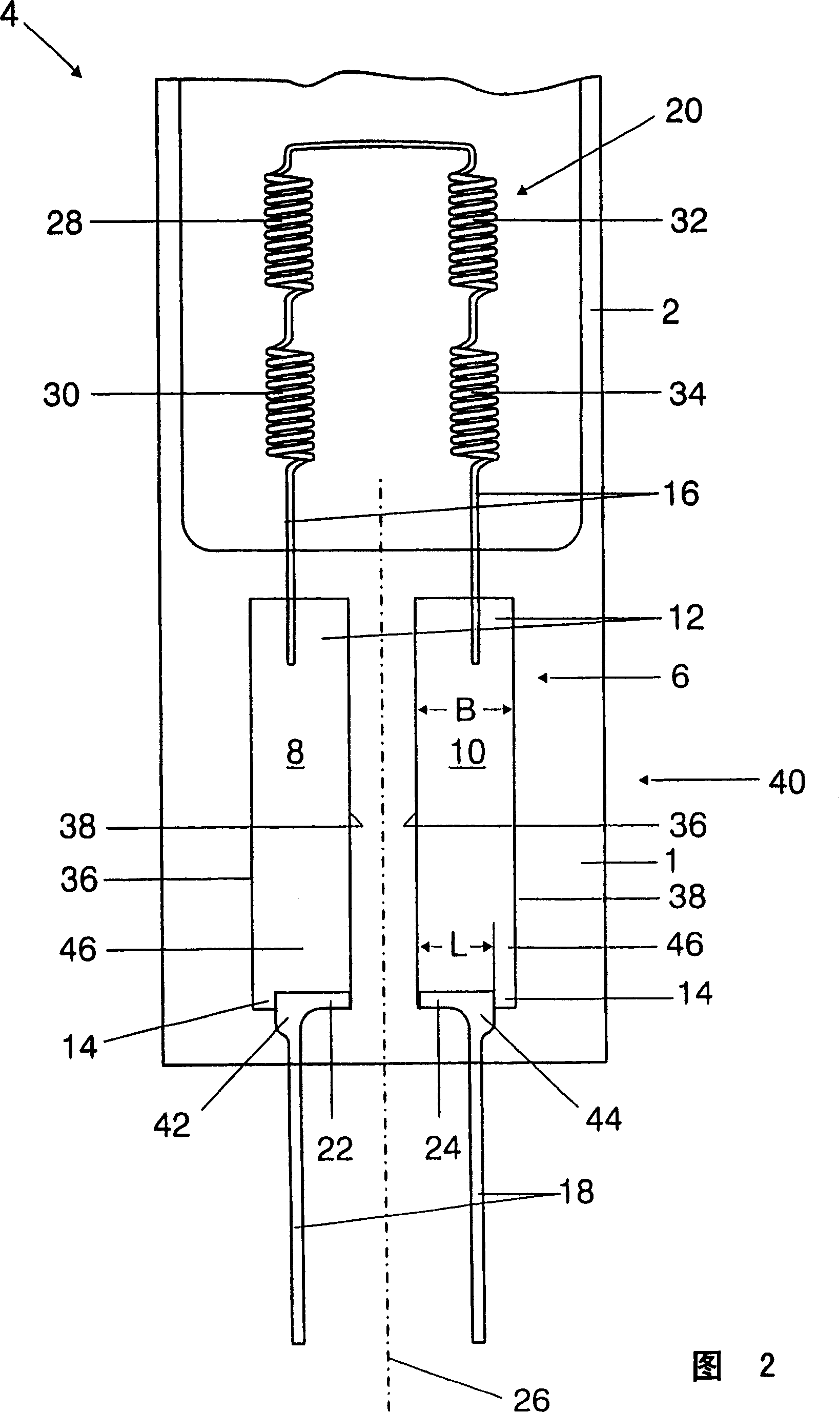
[0020] FIG. 1 shows the closing seal 1 of a lamp envelope 2 made of quartz glass for an electric lamp 4 which has a power supply system 6 according to the invention.

[0021] The feed system 6 has two approximately rectangular molybdenum foils 8 , 10 which are embedded airtight in the end seal 1 of the lamp 4 , wherein an inner feeder is respectively arranged on two opposite narrow sides 12 , 14 . The electrical line 16 and an outer power supply line 18 are used for the electrical energy supply of the luminous means 20 of the lamp 4 . The outer power supply line 18 , which also consists of molybdenum, has lamp-side ends 22 , 24 and is soldered to the molybdenum foils 8 , 10 via these. According to the invention, the ends 22 , 24 of the outer feeder lines 18 are bent at right angles to each other with respect to the longitudinal axes 26 of the molybdenum foils 8 , 10 . Therefore, the spacing a between the thermodynamically critical connection points of the luminous device 20 f...


PUM


Abstract

The subject matter of the disclosure is a power supply system for a lamp, having foils, which are embedded in a gas-tight manner in a pinch seal of the lamp and on which are arranged, in each case on two opposing narrow sides, an inner power supply line and an outer power supply line for the purpose of supplying power to a luminous element of the lamp, the outer power supply lines having lamp-side end sections, which are connected to the foils. According to the invention, the end sections of the outer power supply lines extend at least in sections approximately at right angles to a longitudinal axis of the foils.

Description

technical field [0001] The invention relates to a feed system for a lamp as claimed in the preamble of claim 1 and to a lamp with such a feed system. Background technique [0002] Feed systems of this type are used, for example, for electrical power supply lines in the case of bellows seals made of quartz glass or hard glass for halogen incandescent lamps, discharge lamps or the like. [0003] Since the glass of the neck seal has a significantly lower coefficient of thermal expansion than the power supply lines provided for the electrical energy supply of the luminous means arranged in the lamp vessel, it is not possible to weld the power feed lines directly into the glass of the neck seal. The mechanical stresses caused by the different thermal expansion coefficients will lead to cracking of the lamp envelope and eventually to premature failure of the lamp. For this reason, thin molybdenum foils with sufficient ductility are often applied to achieve hermetic electrical lea...

Claims


Application Information

Patent Timeline
Patent Type & Authority Applications(China)
IPC IPC(8): H01K1/44H01R33/09
CPCH01J61/368H01J61/36H01K1/38H01K1/14H01K1/40
Inventor B·米特勒
Owner PATENT TREUHAND GESELLSCHAFT FUER ELECTRIC GLUEHLAMPEN M B H
Why Eureka
Try Eureka