
Conducting wire sealing bent joint and preparation method thereof

A wire sealing and elbow joint technology, applied in the directions of sealing materials, conductive connections, electrical components, etc., can solve the problems of wire damage to wire solder joints and colloidal sealing performance, large bending space, and high requirements. The sealing performance and the effect of increasing the force bearing point

Active Publication Date: 2017-01-11
CHINA ELECTRONIC TECH GRP CORP NO 18 RES INST
View PDF5 Cites 0 Cited by
  • Summary
  • Abstract
  • Description
  • Claims
  • Application Information

AI Technical Summary

Problems solved by technology

On the one hand, the lead-in and lead-out wires of the plug and socket are welded with solder joints. Since the end of the wires will harden after soldering, and the solder joints generally need to be filled with glue to ensure airtightness, so in the case of a large number of wires It is relatively difficult to bend down, and the required bending space is relatively large. For battery lead wires with limited installation space, it is bound to cause damage to the solder joints and colloid sealing performance of the wires due to too small bending radius; on the other hand, the solder joint plug socket type In the case of more lead-out wires, the volume will be larger, and with the increase of the wires, the number of solder joints will increase, and the intensive solder joint welding will have higher requirements on the welding process and welding workers.

Method used


Image

  • Conducting wire sealing bent joint and preparation method thereof
  • Conducting wire sealing bent joint and preparation method thereof
  • Conducting wire sealing bent joint and preparation method thereof

Examples


Embodiment Construction

[0022] The specific implementation manners of the present invention will be described in detail below in conjunction with the accompanying drawings.

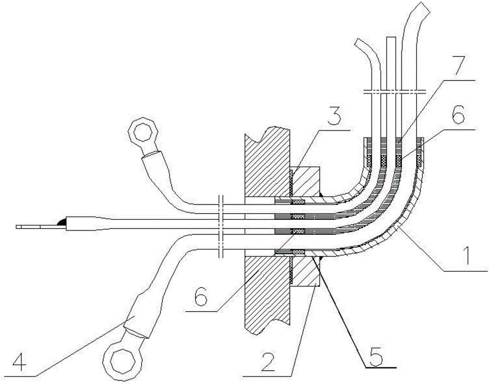
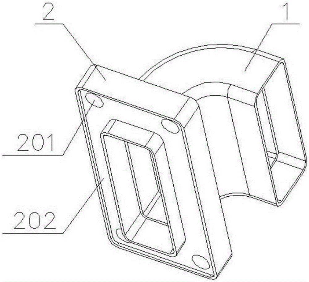
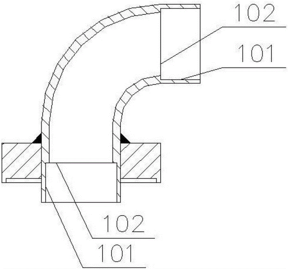
[0023] Such as Figure 1-4 As shown, a wire sealing elbow joint includes an elbow 1, a mounting seat 2 and a sealing wire 4, the inner wall 101 at both ends of the elbow 1 is provided with a limiter 102, and the mounting seat 2 is provided with a The through hole 5 matched with the elbow 1, the elbow 1 passes through the through hole 5 and is welded and fixed with the mounting base 2, and the sieve plate 6 is arranged on the limiting platform 102, and the sieve plate 6 is set There are several wire through holes 601, the sealed wire 4 passes through the wire through holes 601 and the elbow 1, a sealant 7 is injected into the elbow 1, and a mounting hole 201 is provided on the mounting base 2, A sealing limiting groove 202 is provided at the bottom end of the mounting base 2 , and a sealing gasket 3 is arranged in the sealing li...


PUM


Abstract

The invention provides a conducting wire sealing bent joint and a preparation method thereof. The conducting wire sealing bent joint comprises a bent pipe, an installing seat and a sealing conducting wire, wherein a position limiting table is arranged on the inner wall of each of two ends of the bent pipe; a through hole matched with the bent pipe is formed in the installing seat; the bent pipe passes through the through hole to be welded and fixed with the installing seat; a sieve plate is arranged on the position limiting table; a plurality of conducting wire through holes are formed in the sieve plate; the sealing conducting wire passes through the conducting wire through hole and the bent pipe; sealant is injected into the bent pipe for sealing; an installing hole is formed in the installing seat; a sealing position limiting groove is formed in the bottom end of the installing seat; a sealing pad is arranged in the sealing position limiting groove. The preparation method of the conducting wire sealing bent joint comprises the preparation steps of sealing conducting wire preparation, conducting wire passing, first glue sealing and second glue sealing. The conducting wire sealing bent joint has the advantages that the integral structure is compact; the occupied space is small; the preparation process is simple.

Description

technical field [0001] The invention belongs to the technical field of sealing, and in particular relates to a wire sealing elbow and a preparation method thereof. Background technique [0002] With the rapid development of science and technology, the application range of batteries is becoming wider and wider. For chemical power sources, because gas or corrosive substances may be generated inside, in order to avoid damage to the power supply system, the inside of the battery is often isolated from the outside world. This requires that the battery casing is in a sealed state, and at the same time, there is a power supply line drawn from the inside of the battery. Therefore, the sealing of the lead-out power supply line is also an important factor affecting the overall sealing performance of the battery case. [0003] In most cases, the internal lead wire of the battery is sealed by installing and sealing the solder joint plug socket and the shell, sealing the solder joint w...

Claims


Application Information

Patent Timeline
Patent Type & Authority Applications(China)
IPC IPC(8): H01M2/08H01M2/20H01M2/32H01M50/184H01M50/188H01M50/503H01M50/571
CPCH01M50/183H01M50/50H01M50/571Y02E60/10
Inventor 杨朝蓬陈永杰王兴贺段志宇丁志强
Owner CHINA ELECTRONIC TECH GRP CORP NO 18 RES INST
Learn More