Jumper feeding device

A technology of feeding device and jumper cap, which is applied to electrical components, electrical components, etc., can solve the problems of time and manpower waste, low work efficiency, etc.

Inactive Publication Date: 2006-07-12
GIGA BYTE TECH CO LTD
View PDF0 Cites 3 Cited by
  • Summary
  • Abstract
  • Description
  • Claims
  • Application Information

AI Technical Summary

Problems solved by technology

However, since the jumper switch 1 is small in size, and the positions of the jumper caps 12 socket pins 11 of the jumper switch 1 are not the same according to the different assembly positions, the jumper switches are manually inserted one by one. The cap 12 is socketed on the appropriate two pins 11, which will cause a lot of waste of time and manpower, and make the work efficiency very low

Method used


Image

  • Jumper feeding device
  • Jumper feeding device
  • Jumper feeding device

Examples


Embodiment Construction

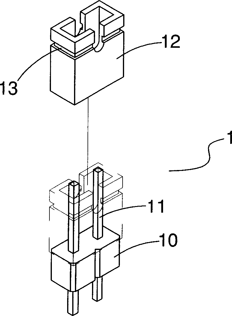
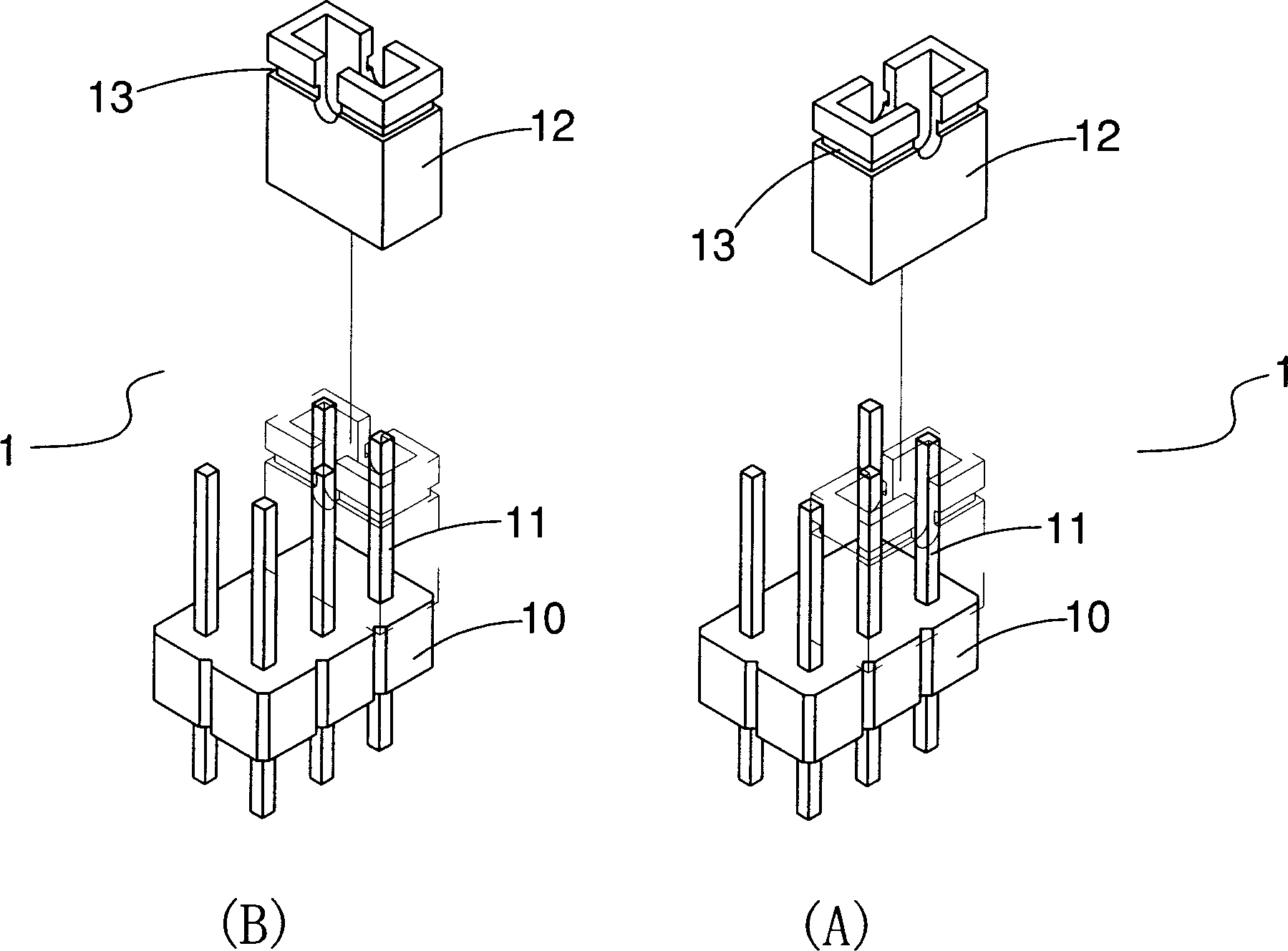
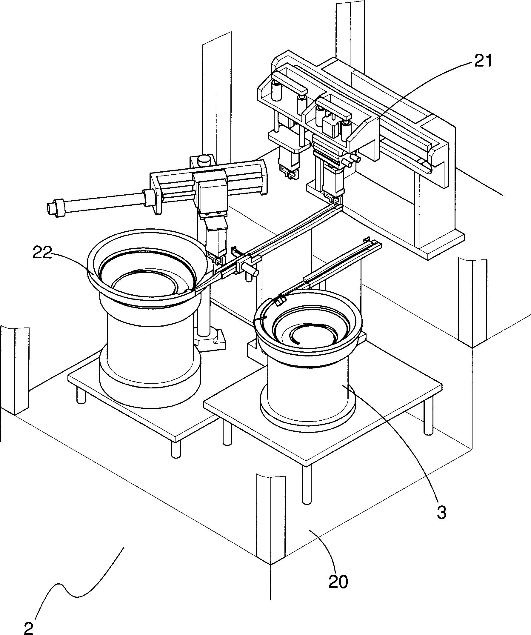
[0047] like image 3 As shown, an automatic assembly machine 2 for automatically inserting and combining the jumper cap 12 on the pin seat 10, the automatic assembly machine 2 is provided with an automatic plugging device 21, a pin seat feeding Device 22 and a jumper cap feeding device 3, wherein:

[0048] The automatic insertion device 21 is used to automatically insert a jumper cap 12 on two longer pins 11 of a pin seat 10, and transport the assembled jumper switch 1 to a collection place;

[0049] Pin seat feeding device 22, used to transport the pin seat 10 to the assembly position of the automatic plugging device 21;

[0050] The jumper cap feeding device 3 is used to turn the jumper cap 12 into a correct assembly direction and transport it to the assembly position of the automatic plugging device 21 .

[0051] like Figure 4 As shown, the jumper cap feeding device 3 includes:

[0052] A feeding tray 30 includes a material trough 300 for the jumper cap 12 to be accomm...


PUM


Abstract

Present invention discloses a jumper cap feeder for turning jumper cap to right assembling direction. It contains feed disk including batch bin for holding jumper cap to form cone surface wall with an outlet, a spiral guided groove, feed disk making jumper cap being delivered to said outlet along spiral guided groove, a screen portion connected with outlet of spiral groove, including a incline extended to said batch bin, a leading rib on incline surface for leading jumper cap having right assembling direction to opposite side, and a guideway connected with feed disk, including a leading-in end, a leading-out end and a guided groove from leading-in end to leading-out end, leading-in end connected with screen portion. Said jumper cap feeder can save a lot of time and manpower with high work efficiency.

Description

technical field [0001] The invention relates to a technology of automatic screening, transmission and direction guiding of electronic parts, especially a technology that can automatically guide the jumper cap of the jumper switch to the assembly direction so as to facilitate the socket combination on the pin of the pin seat installation. Background technique [0002] Jumper switch (jumper) is a movable switch used to determine short circuit or open circuit on the circuit board, such as figure 1 As shown, it usually consists of a pin seat 10 and a jumper cap 12, wherein the pin seat 10 includes a plurality of pins 11 for the jumper cap 12 to be sleeved, when the user sets the jumper cap 12 therein When the two pins 11 are connected to form a short circuit, then some system status can be set. The jumper switch 1 is most commonly used on the motherboard and the expansion card. [0003] figure 1 is a jumper switch 1 with a single-row pin seat 10, and figure 2 It is a jumper...

Claims


Application Information

Patent Timeline
Patent Type & Authority Applications(China)
IPC IPC(8): H05K13/02
Inventor 蔡志伟杨胜安萧奇邦林朝熙翁仁龙孙义雄陈进佳陈威廷李建坤周坤信
Owner GIGA BYTE TECH CO LTD
Why Eureka
Try Eureka