Compressor
A technology for compressors and compression mechanisms, applied in the field of compressors, which can solve problems such as reduced compressor efficiency and increased gas pressure loss
- Summary
- Abstract
- Description
- Claims
- Application Information
AI Technical Summary
Problems solved by technology
Method used
Image
Examples
no. 1 Embodiment
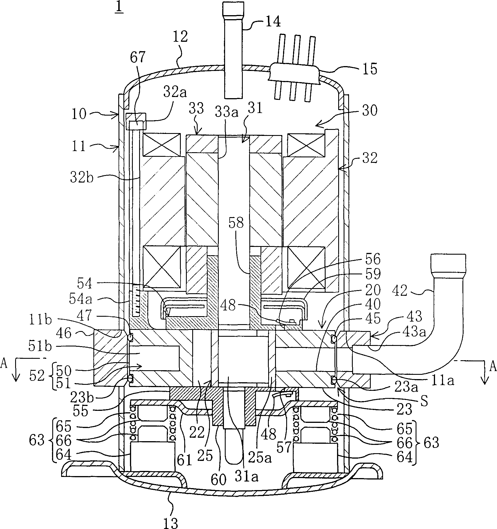
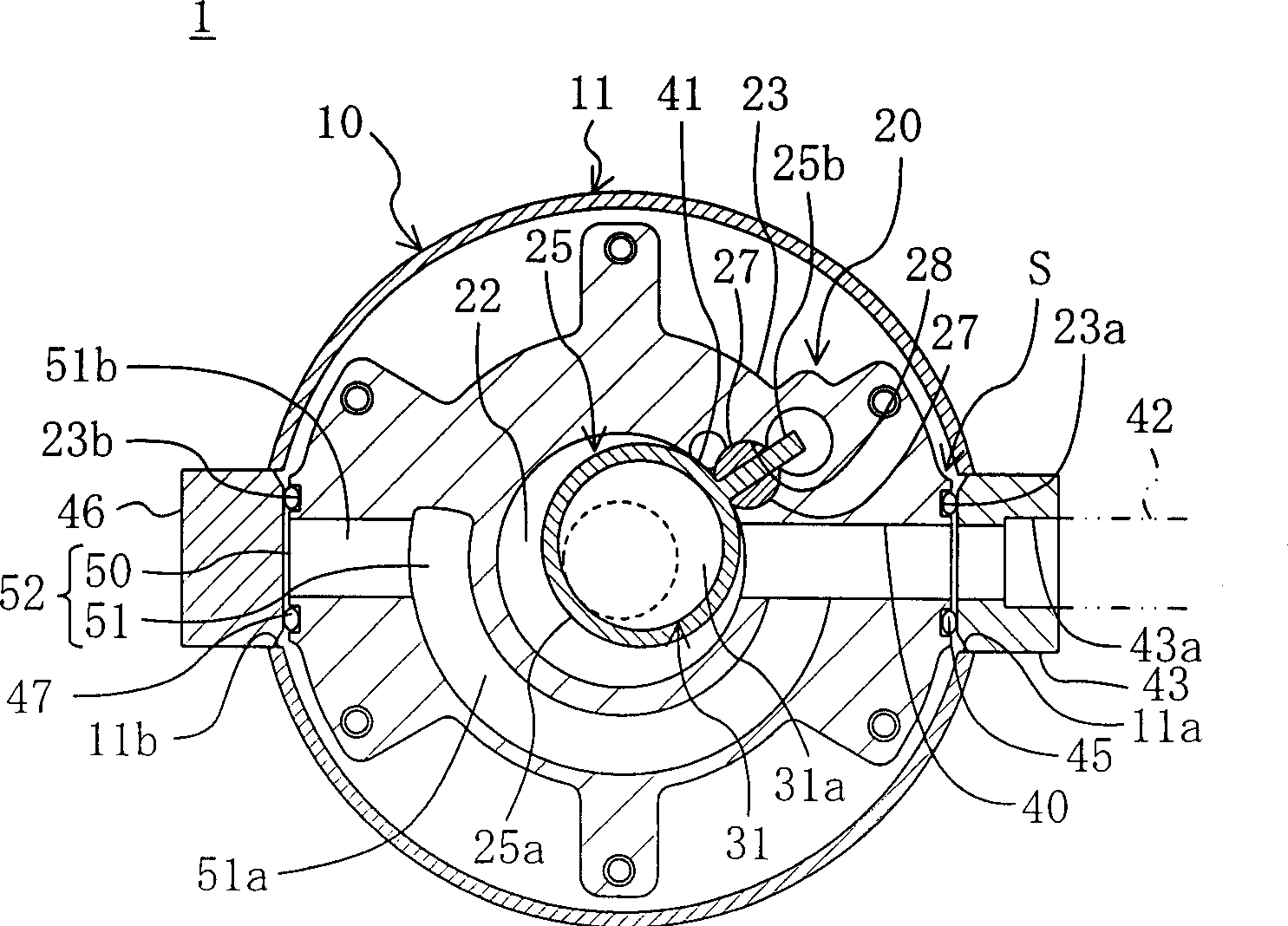
[0115] figure 1 This is the invention according to the first embodiment of the present invention. In this first embodiment, the case where the present invention is applied to a so-called rocking piston type rotary compressor 1 is shown. The compressor 1 performs a refrigerant compression process in the refrigeration cycle of the air conditioner.
[0116] In the compressor 1 described above, the compression mechanism 20 and the motor 30 are accommodated in the airtight container 10 . The drive shaft 31 of the compression mechanism 20 has its axial direction in the up-down direction. The motor 30 is provided on the upper side of the compression mechanism 20 and connected to the drive shaft 31 of the compression mechanism 20 . The motor 30 is integrated with the compression mechanism 20 elastically supported in the airtight container 10 by the support mechanism 63 .
[0117] The airtight container 10 includes: a cylindrical shell 11 that is long in the vertical direction, a bo...
no. 2 Embodiment
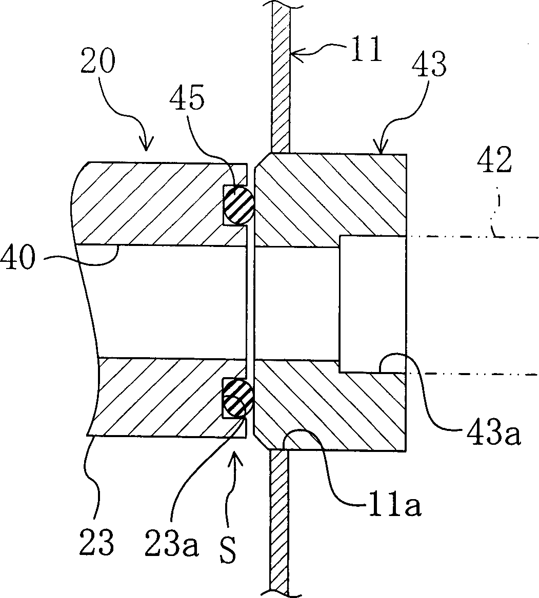
[0178] Image 6 A rotary compressor according to a second embodiment of the present invention is shown. The rotary compressor of this embodiment is the same as that of the first embodiment except for the structures of the sealing mechanism S, the interface member 43 and the block member 46 . In the following description, the same parts as those in the first embodiment are given the same symbols, and only the parts different from them will be described in detail.
[0179] In this embodiment, also as Figure 7 As shown, the peripheral portion of the suction passage 40 on the outer surface of the cylinder 23 is a flat surface substantially perpendicular to the radial direction of the cylinder 23, and this flat surface serves as a sealing surface. On the other hand, the front end side portion of the interface member 43 is formed in a cylindrical shape, and this portion constitutes the cylindrical portion 71 . Then, the sealing member 72 is fitted into the cylindrical portion 71...
no. 3 Embodiment
[0205] The third embodiment of the present invention is an embodiment in which the structure of the compressor of the above-mentioned first embodiment is changed. Here, differences between this embodiment and the first embodiment described above will be described.
[0206] Such as Figure 12 and Figure 13 As shown, in the compressor 1 of the present embodiment, the block member 46, the suction pressure chamber 50, and the communication path 51 are omitted. Furthermore, in this embodiment, the shape of the interface member 43 is different from that of the first embodiment described above.
[0207] The interface member 43 of this embodiment is formed in a cylindrical shape. One end of the suction tube 42 is inserted and fixed to the base end side of the through hole 43 a provided in the mouthpiece member 43 . The interface-side insertion hole 11 a provided in the body 11 of the airtight container 10 has a higher lower end and a lower upper end than the compression mechanism...
PUM
 Abstract
Description
Claims
Application Information
 - R&D
- Intellectual Property
- Life Sciences
- Materials
- Tech Scout
- Unparalleled Data Quality
- Higher Quality Content
- 60% Fewer Hallucinations
Browse by: Latest US Patents, China's latest patents, Technical Efficacy Thesaurus, Application Domain, Technology Topic, Popular Technical Reports.
© 2025 PatSnap. All rights reserved.Legal|Privacy policy|Modern Slavery Act Transparency Statement|Sitemap|About US| Contact US: help@patsnap.com


