

Suspension method of mixed magnetic suspension and magnetic suspension system
A magnetic levitation and magnet technology, which is applied in transportation and packaging, electric traction, electric vehicles, etc., can solve the problems of high power consumption and achieve the effects of saving electric energy, reducing levitation power consumption, and levitation power consumption
- Summary
- Abstract
- Description
- Claims
- Application Information
AI Technical Summary
Problems solved by technology
Method used
Image

Examples
Embodiment 1
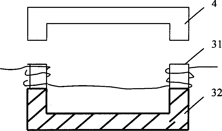
[0026] Such as image 3 As shown, the cross section of the magnet 3 is U-shaped, the two ends of the U-shaped are electromagnets 31, and the middle part is a permanent magnet 32. The two electromagnets 31 and the permanent magnets 32 are fixedly connected together.
[0027] In this embodiment, the magnet 3 is refitted from the original whole electromagnet into a suspension module composed of two electromagnets 31 and a permanent magnet 32 fixedly connected. When the train is not put into operation, the electromagnet 31 is not connected to the excitation current, and the electromagnet 31 does not produce suction, and there is only suction between the permanent magnet 32 and the track 4 . As long as suitable permanent magnets 32 are selected for use, the suction force is not enough to suspend the train, and the train is supported on the track. When the train is put into operation, the excitation current is connected in the electromagnet 31, and an attraction force is also g...
Embodiment 2
[0030] Such as Figure 4 As shown, the cross section of the magnet 3 is U-shaped, the two ends of the U-shaped are electromagnets 31, and the middle part is a permanent magnet 32. The electromagnet 31 and the permanent magnet 32 are installed separately, and the permanent magnet 31 is installed on the up and down moving mechanism. , so that it can move with the up and down moving mechanism. The up and down moving mechanism can adopt the existing technology, which is not limited here.
[0031] The magnitude of the attractive force between the permanent magnet 32 and the track 4 is closely related to the distance between the permanent magnet 32 and the track 4 . The smaller the distance between the permanent magnet 32 and the track 4, the greater the suction force; on the contrary, if the larger the distance between the permanent magnet 32 and the track 4, the smaller the suction force. Therefore, the permanent magnet 32 can be moved up and down by the up and down ...
Embodiment 3
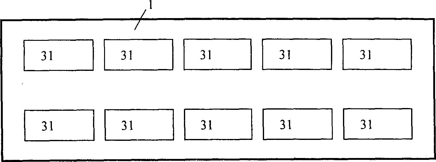
[0036] Such as Figure 5 As shown, the magnet 3 is an independent U-shaped electromagnet 31 and a U-shaped permanent magnet 32, which are installed at the bottom of the vehicle body 1 respectively.
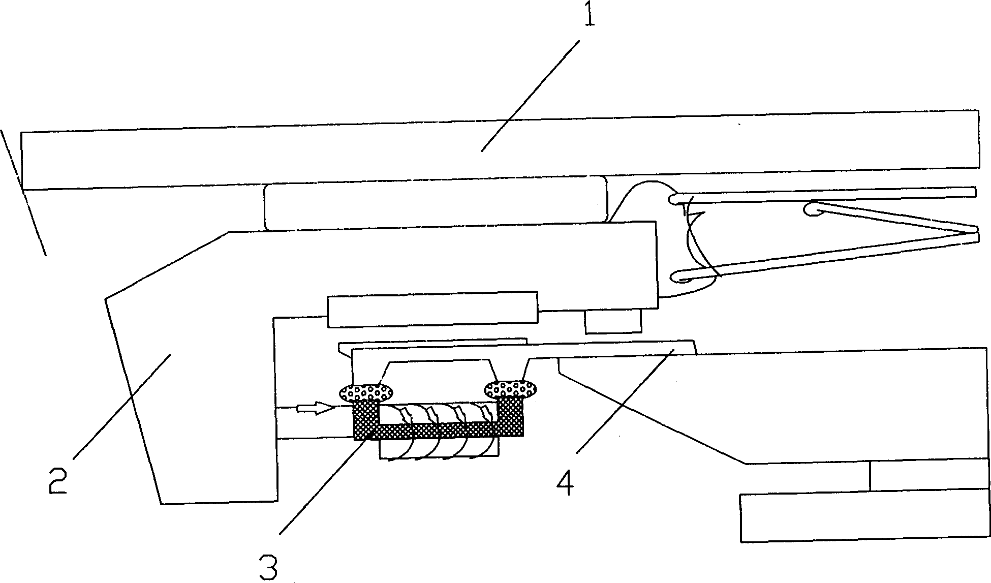
[0037] Several pairs of electromagnets are installed at the bottom of each compartment of the existing maglev train, for example, 5 pairs of electromagnets are installed at the bottom of each compartment of the Japanese LINIMO maglev train. In this embodiment, some of the electromagnets can be replaced by permanent magnets, such as Figure 5 , the three pairs of electromagnets in the middle can be replaced by permanent magnets 32, and the two pairs of electromagnets 31 on both sides are still retained, wherein the levitation principle of the electromagnets is as follows figure 2 As shown, the levitation principle of the permanent magnet is as follows Figure 6 shown.
[0038] When the train is not put into operation, the electromagnet 31 is not connected to the excitation curr...
PUM
 Abstract
Description
Claims
Application Information