Novel ultrasonic clutch

A clutch and ultrasonic technology, applied in the direction of clutches, electric clutches, non-mechanical drive clutches, etc., can solve the problems of difficult automation, slow response speed, unstable operation, etc., and achieve simple and compact structure, strong carrying capacity and flexible operation. Effect

Pending Publication Date: 2018-04-20
SICHUAN UNIV
View PDF20 Cites 1 Cited by
  • Summary
  • Abstract
  • Description
  • Claims
  • Application Information

AI Technical Summary

Problems solved by technology

Traditional clutches have defects such as slow response speed, complex structure, unstable operation, large volume, and difficulty in realizing automation.

Method used


Image

  • Novel ultrasonic clutch
  • Novel ultrasonic clutch
  • Novel ultrasonic clutch

Examples


Embodiment

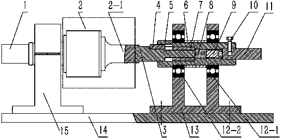
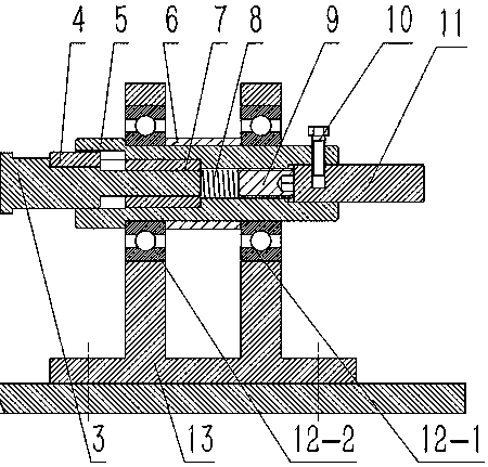
[0019] like figure 1 As shown, a new type of ultrasonic clutch includes a drive shaft (1), an ultrasonic vibration mechanism (2), a transducer (2-1), a driven shaft (3), a C-type common flat key (4), a driven Shaft sleeve (5), positioning sleeve (6), linear bearing (7), preload spring (8), preload bolt (9), rolling bearing (12), bolt (10), output shaft (11). The supporting device includes a bearing support (13) (15) and a base (14); the ultrasonic clutch and the driven assembly are fixed on the base (14) through the bearing seat (15) (13), and the replacement The three coaxial assemblies of the energy device (2-1), the driven shaft (5), and the output shaft (11).

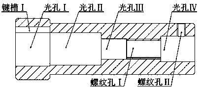
[0020] In order to ensure that the driven shaft moves axially along the driven shaft sleeve under the action of pretightening force and ultrasonic suspension force during operation, the linear bearing (7) is installed in light hole II with interference fit; the driven shaft (3) Installed coaxially with the driven ...


PUM


Abstract

The invention discloses a novel ultrasonic clutch. The novel ultrasonic clutch is composed of an ultrasonic vibration mechanism, a driven assembly and an output shaft; the driven assembly comprises adriven shaft, a driven shaft sleeve, a C-shaped general flat key, a linear bearing, a pre-tightening spring, a pre-tightening bolt, a positioning sleeve and rolling bearings; key grooves are formed inthe driven shaft and the driven shaft sleeve, and the driven shaft and the driven shaft sleeve are connected through keys; tin the working process, the keys play a role of guiding and transmitting the torque; the driven shaft, the linear bearing, the pre-tightening spring and the pre-tightening bolt are arranged in the driven shaft sleeve; the pre-tightening spring and the pre-tightening bolt provide the pre-tightening force for the driven shaft so that the end surface of the driven shaft can be tightly attached to the end surface of a transducer; and in the working process, high-frequency voltage excitation is applied to the ultrasonic vibration mechanism, high-frequency longitudinal vibration is generated by utilizing the inverse piezoelectric effect of piezoelectric ceramics, a near-field suspension phenomenon is generated on the two joint surfaces, when the radiation pressure is smaller than the pre-tightening force, the driving end and the driven end are in differential rotation,and when the radiation pressure is greater than the pre-tightening force, the driving end is separated from the driven end. The novel miniaturized and light-weight ultrasonic clutch has the advantages of being simple in structure and easy to machine and assemble.

Description

technical field [0001] The invention belongs to a novel ultrasonic clutch, in particular to a novel clutch device which uses ultrasonic longitudinal vibration to generate near-field suspension. Background technique [0002] As an important part of the mechanical motion mechanism, the clutch is the link between the power system and the transmission system, and plays the role of separation and engagement of motion. It is widely used in aerospace, home appliances, office machines, industrial robots and other fields. Traditional clutches have defects such as slow response speed, complex structure, unstable operation, large volume, and difficulty in realizing automation. Contents of the invention [0003] In order to overcome the deficiencies of the existing technology and meet the needs of development and change, the present invention combines the characteristics of high-speed response of ultrasonic longitudinal vibration, large near-field suspension force of ultrasonic waves,...

Claims


Application Information

Patent Timeline
Patent Type & Authority Applications(China)
IPC IPC(8): F16D28/00
CPCF16D28/00
Inventor 傅波林波柳晓东李彬彬冉振胡涛张园周瑞
Owner SICHUAN UNIV
Why Eureka
Try Eureka