Pressure injection-moulded hot melt sealed pipe joint and sealing method thereof

A technology of hot-melt sealing and pipe joints, which is applied in the direction of non-detachable pipe connections, pipes/pipe joints/fittings, passing components, etc., which can solve the problems of easy damage to the butt joint rubber ring, complicated butt joint operation, and high joint cost to achieve sealing Effective effect, wide application range and low cost

Inactive Publication Date: 2006-07-26
李富春
View PDF2 Cites 16 Cited by
  • Summary
  • Abstract
  • Description
  • Claims
  • Application Information

AI Technical Summary

Problems solved by technology

[0004] In order to solve the problems of the existing pipe installation and use that the butt joint rubber ring is easily damaged, the seal is not tight enough to cause leakage, the joint cost is high, and the joint operation is complicated, the present invention provides a pressure injection molded hot melt seal Type pipe joint and its sealing method

Method used


Image

  • Pressure injection-moulded hot melt sealed pipe joint and sealing method thereof
  • Pressure injection-moulded hot melt sealed pipe joint and sealing method thereof

Examples


specific Embodiment approach 1

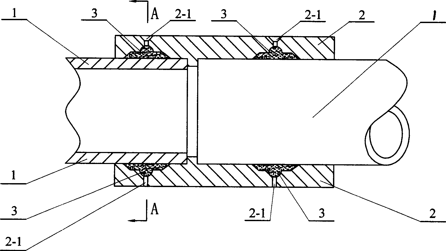
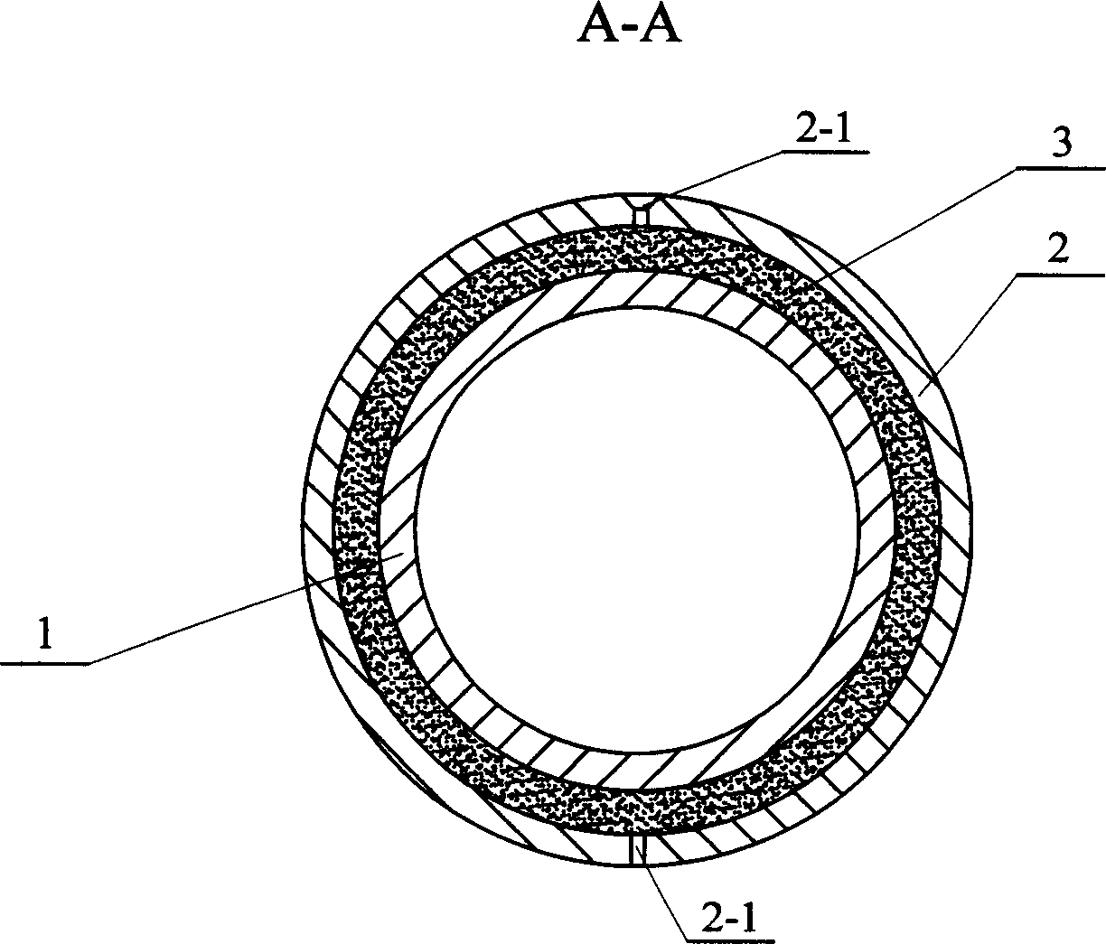
[0010] Specific implementation mode one: see figure 1 and figure 2 The pressure injection molded hot-melt sealed pipe joint of this specific embodiment is composed of a connecting pipe fitting 2 and a hot-melt adhesive layer 3, and at least two pairs of radial melt glue injections are provided at different positions on the outer wall of the connecting pipe fitting 2 in the axial direction. In hole 2-1, a hot melt adhesive layer 3 is solidified in the gap between the outer surface of the butt end of the pipe 1 and the inner surface of the connecting pipe.

specific Embodiment approach 2

[0011] Specific implementation mode two: see figure 1 and figure 2 The difference between this embodiment and Embodiment 1 is that: the inner surface of the connecting pipe 2 is provided with at least one ring-shaped flow channel, and the ring-shaped flow channel is connected to a pair of radial melt injection holes 2- 1 is connected, and a hot melt adhesive layer 3 is solidified in the cavity of the annular flow channel. The annular flow channel of the above-mentioned connecting pipe fittings and a pair of pouring holes together constitute an annular cavity with a socket on the bonding surface. When the hot melt adhesive is sprayed into the annular flow channel through the filling hole, the hot melt adhesive will flow along the flow channel Flow until the entire annular cavity is filled, and then cool and solidify to form a hot melt adhesive layer. Other compositions and connections are the same as in the first embodiment.

specific Embodiment approach 3

[0012] Specific implementation mode three: see figure 1 and figure 2 The difference between this specific implementation and specific embodiment 1 is: a pair of radial melt glue injection holes 2-1 are respectively provided on the outer walls of the first and last ends of the connecting pipe fitting 2, and the first and last of the connecting pipe fitting 2 The inner surfaces of both ends are respectively provided with a circle of annular flow passages, the annular flow passages on the inner surface of the head end of the connecting pipe fitting 2 communicate with a pair of radial melt injection holes 2-1 on the outer wall of the head end, and the connecting pipe fittings 2. The annular flow channel on the inner surface of the end communicates with a pair of radial melt injection holes 2-1 on the outer wall of the end. Other compositions and connections are the same as in the first embodiment. This specific embodiment can be used to connect the butt ends of two pipelines. ...


PUM


Abstract

The invention relates to a hot melt sealing tube interface of pressure injection and relative sealing method, which relates to the tube connection technique, and solves the problems of vulnerable connection sealing ring, worse sealing, leakage, high cost and complex operation in present installment and usage. The invention is formed by the connection tube (2) and the hot melt adhesive layer (3). Wherein, there are at least two couples of radial hot melt adhesive filling holes (2-1) at different parts of axial outer wall of said connection tube (2); and the hot melt adhesive layer (3) is solidified in the gap between the outer surface of tube connection end (1) and the inner surface of connection tube. The invention uses pressure injection to fill the melt hot melt adhesive into the tube and the connection tube to form an annular hot melt adhesive layer to seal and fix the tube.

Description

technical field [0001] The invention belongs to the pipeline connection technology, and in particular relates to a hot-melt sealing pipeline interface of pressure injection molding and a sealing method thereof. Background technique [0002] The most commonly used pipe joints in the past mainly include socket rubber ring seals and electric hot-melt welding seals. The socket rubber ring seals are poor in aging resistance and chemical solvent resistance due to the socket seal rubber ring, and the sealant during installation The ring is easily damaged by shear force, which limits its application range; the butt welding of electrothermal fusion welding will cause the inner hole to shrink, so that the pipe will form resistance and cause invisible flow loss. There is also a socket electric hot-melt welding that is not commonly used, which requires high processing size of the pipe socket. If the matching gap between the inner diameter joint surface is too large, it is prone to the p...

Claims


Application Information

Patent Timeline
Patent Type & Authority Applications(China)
IPC IPC(8): F16L13/12
Inventor 李富春
Owner 李富春
Why Eureka
Try Eureka