1+1 separated switch power supply module
A switching power supply, split structure technology, applied in the direction of adjusting electrical variables, instruments, conversion equipment that can be converted to DC without intermediate conversion, etc., can solve the problems of no indicator light, short life of high and low voltage components, and complicated wiring Achieve the effect of solving the influence of high temperature, prolonging the service life and wide application range
- Summary
- Abstract
- Description
- Claims
- Application Information
AI Technical Summary
Problems solved by technology
Method used
Image

Examples
Embodiment Construction
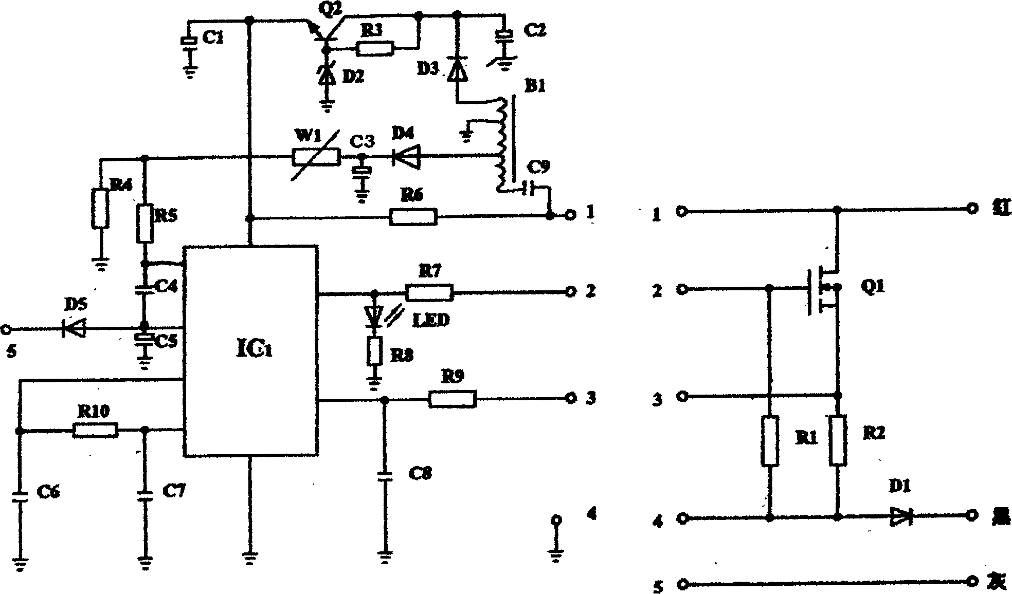
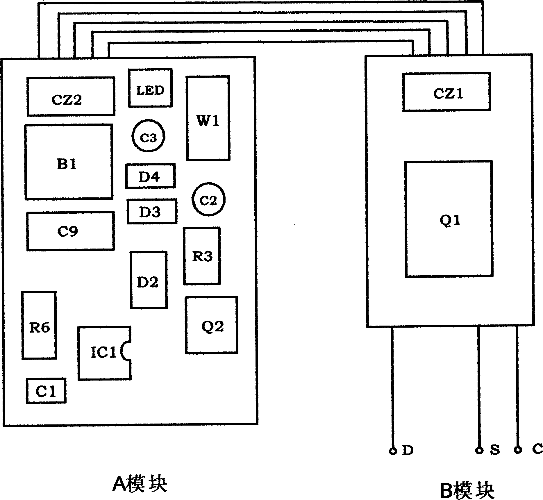
[0012] The two module main boards of the present invention are respectively packaged in two housings, and the A module and the B module of the split structure are connected by connectors (CZ1, CZ2) at both ends of the multi-core flat wire, and the power supply is turned on during use, (R6 ) to charge (C1), and when it is charged to a certain voltage, the integrated circuit (ICI) starts to work, and the output pulse pushes the switch tube (Q1) to be turned on and off, and the pulse signal is fed back through the transformer (B1) and the DC blocking capacitor (C9) To the secondary pole, all the way is rectified by the diode (D3), filtered by the capacitor (C2), and after the voltage is stabilized by the triode (Q2), bias resistor (R3), and voltage regulator (D2), it provides the power required for the operation of the integrated circuit (IC1) .
[0013] The other channel passes through (D4) and (C3) for voltage stabilization and sampling, and the potentiometer (W1) adjusts the s...
PUM
 Abstract
Description
Claims
Application Information
 - Generate Ideas
- Intellectual Property
- Life Sciences
- Materials
- Tech Scout
- Unparalleled Data Quality
- Higher Quality Content
- 60% Fewer Hallucinations
Browse by: Latest US Patents, China's latest patents, Technical Efficacy Thesaurus, Application Domain, Technology Topic, Popular Technical Reports.
© 2025 PatSnap. All rights reserved.Legal|Privacy policy|Modern Slavery Act Transparency Statement|Sitemap|About US| Contact US: help@patsnap.com