Shape memory alloy driven miniature guide device for interventional blood vessel operation

A memory alloy, micro-device technology, applied in the field of shape memory alloys, can solve problems such as effectiveness and safety limitations

Inactive Publication Date: 2006-08-02
HARBIN INST OF TECH
View PDF0 Cites 12 Cited by
  • Summary
  • Abstract
  • Description
  • Claims
  • Application Information

AI Technical Summary

Problems solved by technology

[0003] In order to solve the problem that the effectiveness and safety of the operation are limited by manual control of catheter guidance in the existing interventional surgery, a guide micro-device driven by shape memory alloy for vascular interventional surgery is pr

Method used


Image

  • Shape memory alloy driven miniature guide device for interventional blood vessel operation
  • Shape memory alloy driven miniature guide device for interventional blood vessel operation
  • Shape memory alloy driven miniature guide device for interventional blood vessel operation

Examples


specific Embodiment approach 1

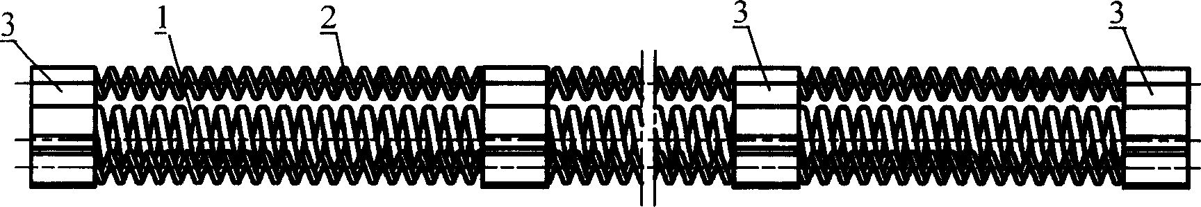
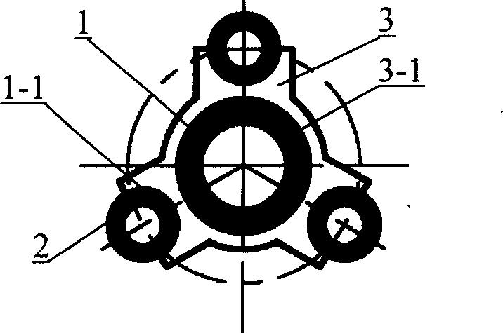
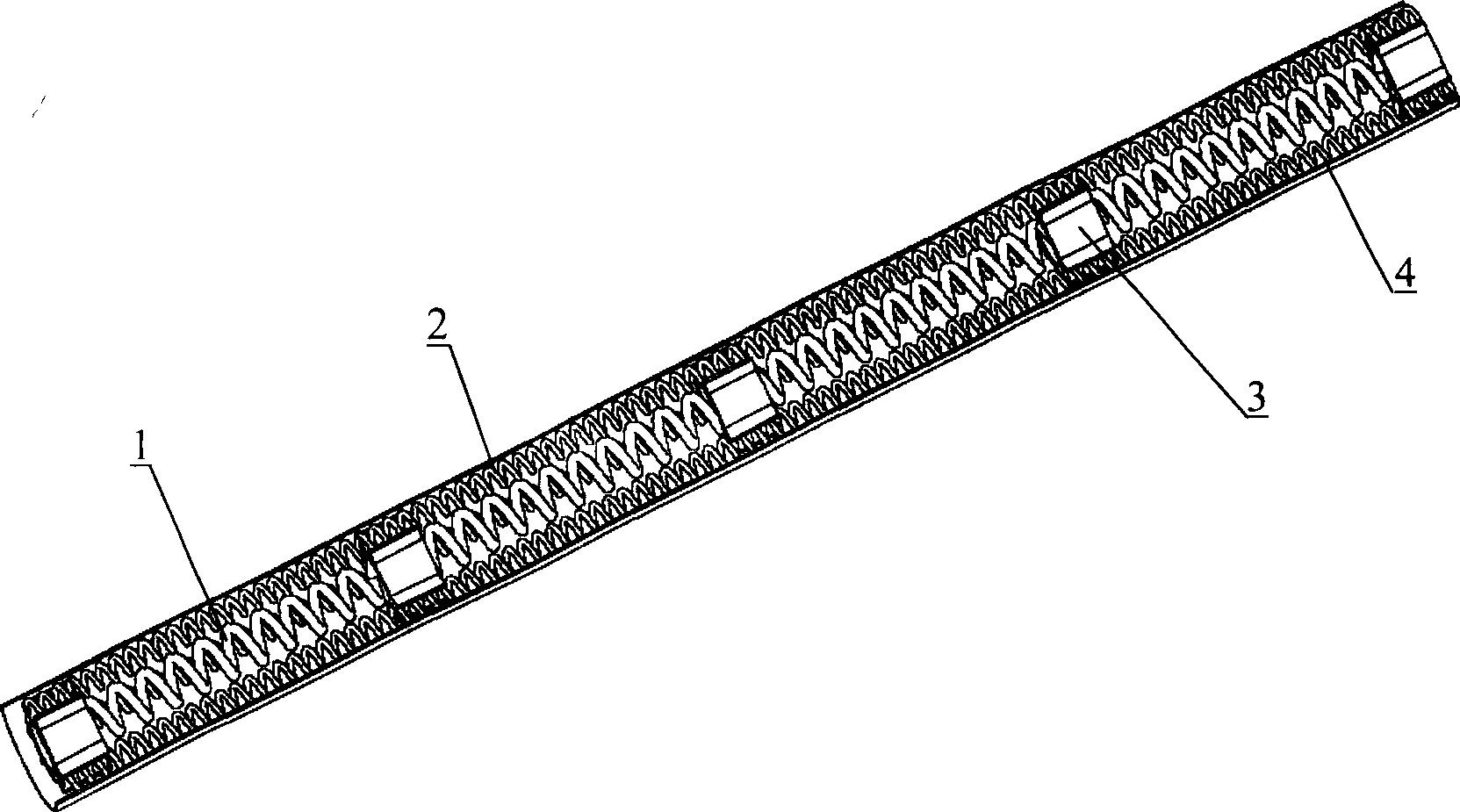
[0005] Specific implementation mode one: (see Figure 1-Figure 5 ) This embodiment consists of a bias spring 1, three shape memory alloy (SMA) springs 2 and two connectors 3, the bias spring 1 is a compression spring, the connector 3 has a central through hole 3-1, and the bias The spring 1 passes through the central through hole 3-1 on the two connectors 3 and is fixedly connected with the central through hole 3-1. The three shape memory alloy springs 2 are evenly distributed on the outside of the bias spring 1 and are respectively connected with the The outer surface of part 3 is fixedly connected as a whole. Since the tensile strength of the NiTi alloy is above 1000Mpa, the elongation is above 20%, and the fatigue life reaches 10 7 Second, the damping characteristic is 10 times higher than that of ordinary springs, and its corrosion resistance is better than the best medical stainless steel at present. The bias spring described in this embodiment can be selected as a shape...

specific Embodiment approach 2

[0006] Specific implementation mode two: (see Figure 1-Figure 5 ) The difference between this embodiment and the specific embodiment 1 is that the connection between the connecting member 3 and the bias spring 1 is a concave arc surface 1-1, and the shape and size of the concave arc surface 1-1 are the same as The outer diameter of the bias spring 1 matches. Other compositions and connections are the same as in the first embodiment. Because the shape and size of the inner concave arc surface 1-1 match the outer diameter of the bias spring 1, the contact area between the connector 3 and the bias spring 1 is the largest, and when the SMA spring 2 undergoes a phase change, the present invention is guaranteed Action reliability.

specific Embodiment approach 3

[0007] Specific implementation mode three: (see Figure 1-Figure 5 ) The difference between this embodiment and the first or second embodiment is that the connector 3 is made of an insulating material or a conductive material whose outer surface is coated with an insulating film. Other compositions and connections are the same as those in Embodiment 1 or Embodiment 2. This embodiment avoids the problem that the performance of the whole micro-device is affected by the conduction of electricity between the SMA springs or between the SMA spring and the bias spring.


PUM

PropertyMeasurementUnit
Tensile strengthaaaaaaaaaa

Abstract

The shape memory alloy (SMA) driven miniature guide device for interventional blood vessel operation is the application of SMA in biomedical engineering technology to raise the effectiveness and safety of operation with duct guiding. The miniature guide device includes one bias spring, at least three SMA springs and at least two connectors with central hole. The bias spring penetrates through central holes for fixation, and SMA springs are distributed homogeneously outside the bias spring and connected integrally with the outside of the containers. By means of SMA, the miniature guide device may be used in controlling the motion direction of duct or wire actively from the front end for accurate location so as to shorten operation period, reduce patientí»s pain and raise operation quality.

Description

technical field [0001] The invention relates to the application of shape memory alloy (SMA) to the technical field of biomedical engineering. Background technique [0002] Beginning in the early 1990s, interventional minimally invasive surgery techniques began to be applied to the treatment of vascular diseases. During the operation, the doctor inserts the catheter into the blood vessel, and under the guidance of the X-ray image, extends the catheter to the target position, and then completes certain medical procedures at the target position. Such interventional surgery can not only effectively solve vascular diseases, but also has many outstanding advantages, such as greatly shortening the operation time, greatly reducing the pain of patients, and shortening the recovery time from months to days. Due to these advantages, interventional surgery is adopted by more and more doctors and accepted by more and more patients. However, conventional vascular catheters use a manual ...

Claims


Application Information

Patent Timeline
IPC IPC(8): A61B17/00A61F2/00A61F2/82
Inventor 付宜利李显凌马炘梁兆光刘浩王树国
Owner HARBIN INST OF TECH
Why Eureka
Try Eureka