
Hydraulic support leg

A technology of hydraulic support legs and support legs, which is applied in the field of hydraulic devices, can solve the problems of restricting the working capacity of electric handling stackers, increase the width and load, and cannot increase year-on-year, so as to expand the use performance, work efficiency, and installation. and ease of use, the effect of increasing height and weight

Inactive Publication Date: 2006-08-02
NINGBO RUYI
View PDF0 Cites 11 Cited by
  • Summary
  • Abstract
  • Description
  • Claims
  • Application Information

AI Technical Summary

Problems solved by technology

And the described electric handling stacker truck that is currently used in the warehouse requires the height of the goods to be lifted higher and higher, but the width between the car body of the stacker truck and its left and right wheel legs cannot be increased year-on-year. Large; when the ratio between the lifting height and the width between the left and right wheel legs is greater than 5, the electric pallet truck will lose its stability when the load is raised or the goods are picked up from high altitude, and it is easy to tip over
[0003] At present, there are all kinds of electric pallet trucks on the market, but most of them have the problem of coordination between the width between the left and right wheel legs of the electric pallet truck and the ratio of load lifting and high-altitude picking. , which restricts the working capacity of the electric pallet truck itself
In order to prevent the goods from tipping over or even falling during the process of lifting the load and picking up goods from high altitude and causing damage to the goods, the width between the left and right wheel legs of the existing electric stacker truck must be restricted. , which restricts the working efficiency of electric pallet trucks currently on the market

Method used


Image

  • Hydraulic support leg
  • Hydraulic support leg
  • Hydraulic support leg

Examples


Embodiment Construction

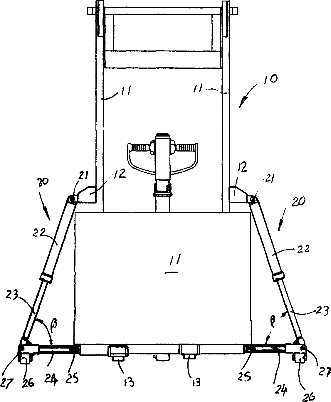
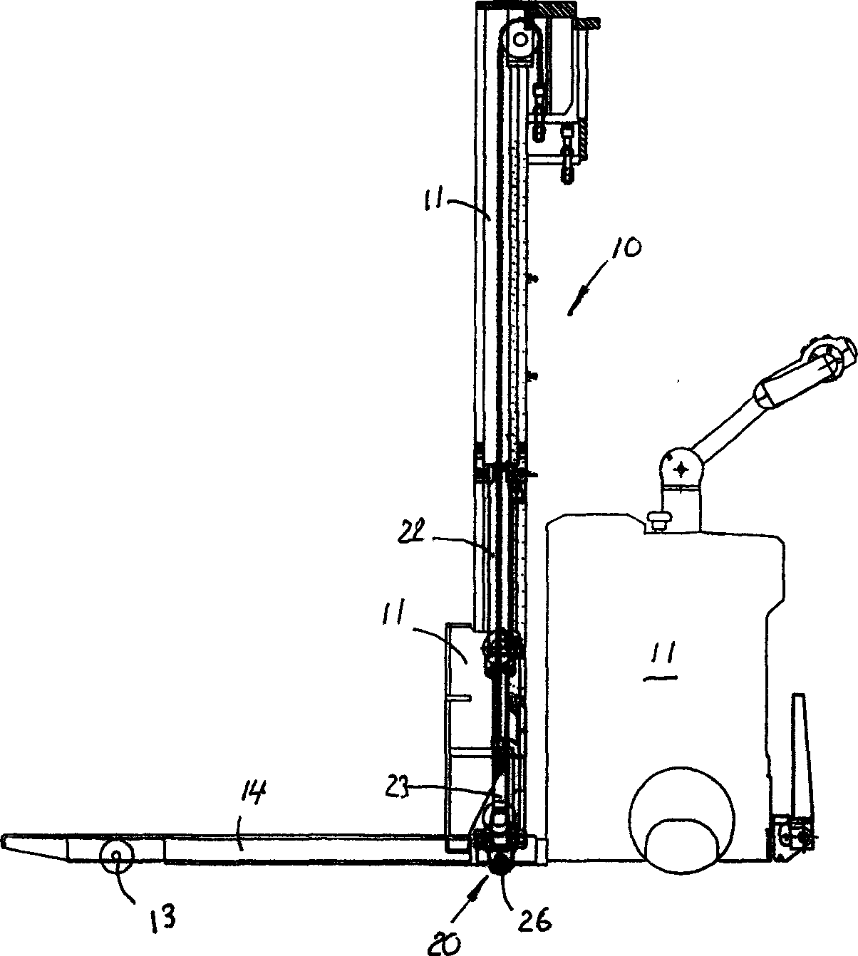
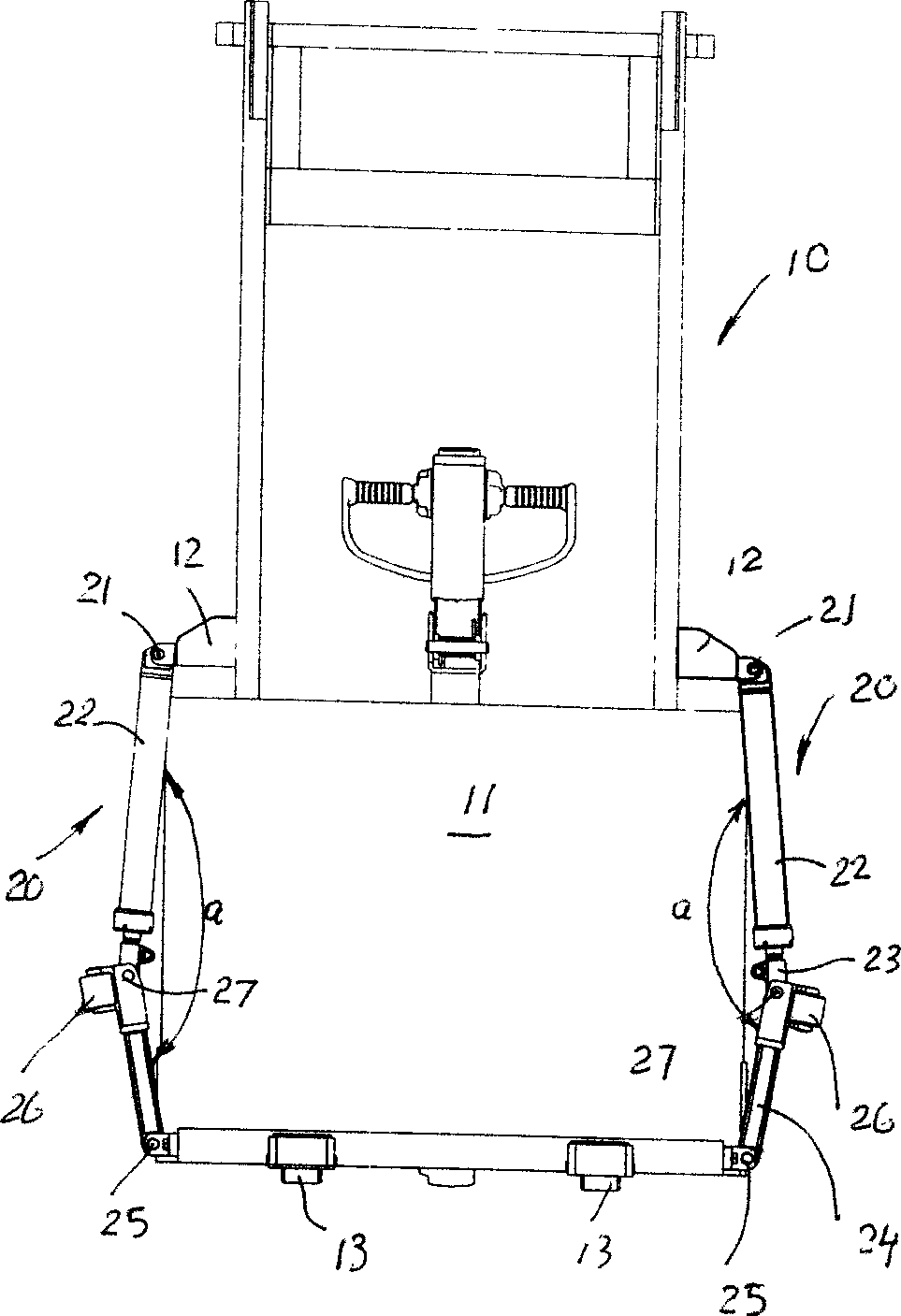
[0019] In order to reduce the width between the left and right wheel legs of the electric stacker truck and the volume of the car body, and to increase the height and weight of the goods to be lifted, the present invention adopts the configuration of hydraulic support legs on both sides of the electric stacker truck frame. . When stacking high loads or picking up goods from high altitude, put down the hydraulic support legs, and when carrying, lower the goods and gather the hydraulic support legs. The present invention will be further described in detail below in conjunction with the accompanying drawings and embodiments.

[0020] Figure 1 to Figure 3 One embodiment of the hydraulic support leg of the present invention is shown. The hydraulic support legs 20 of the present invention are respectively arranged on the left and right sides of the stacker truck 10 with the vehicle body 11 and the running wheels 13, and work synchronously.

[0021] The hydraulic support leg incl...


PUM


Abstract

The hydraulic support legs are set in the right and left sides of electric stacking vehicle. Each of the hydraulic support legs includes one hydraulic cylinder and its piston rod, one rotating pinshaft in the lower end of the piston rod, one movable support leg connected to the pinshaft, one servo wheel connected outside the upper end of the support leg, one leg supporting pinshaft in the lower end of the support leg and connected to the lower part of the vehicle body, and one vehicle pinshaft set in the upper end of the hydraulic cylinder connected to the middle part of the vehicle body. When the stacking vehicle lifts cargo, hydraulic oil enters to the cavities of the hydraulic cylinders, the pistons stretch downwards to make the support legs rotate downwards to the ground and the servo wheels contact the ground to support the stacking vehicle stably. The present invention can raise the performance of the stacking vehicle.

Description

technical field [0001] The invention relates to the field of hydraulic devices, in particular to a hydraulic support leg of a stacker truck. It is mainly used on high-lift stacker trucks to realize good stability of the car body when the stacker trucks are lifted; the invention is also suitable for supporting use on various transport tools for carrying and lifting goods. Background technique [0002] At present, with the rapid development of modern industry and logistics industry, a large number of products need to be transported and stacked after they are produced. The electric stacker is an efficient handling tool for indoor stacking, with the characteristics of small size and small turning radius. And the described electric handling stacker truck that is currently used in the warehouse requires the height of the goods to be lifted higher and higher, but the width between the car body of the stacker truck and its left and right wheel legs cannot be increased year-on-year....

Claims


Application Information

Patent Timeline
Patent Type & Authority Applications(China)
IPC IPC(8): B66F13/00
Inventor 蔡国俊
Owner NINGBO RUYI
Learn More