Non-reciprocal circuit element

A circuit element and electrode technology, applied in the field of non-reciprocal circuit elements, can solve the problems of affecting productivity, disadvantageous thinning, and increasing cost, and achieve the effect of good productivity

Inactive Publication Date: 2006-08-02
ALPS ALPINE CO LTD
View PDF1 Cites 3 Cited by
  • Summary
  • Abstract
  • Description
  • Claims
  • Application Information

AI Technical Summary

Problems solved by technology

[0007] In the conventional non-reciprocal circuit element, since the ferrite magnetic body 55 is mounted on the flat bottom plate 53a of the second yoke 53, it is not only disadvantageous for thinning, but also needs to use the resin case 54 to enclose the ferrite body. The positioning of the magnetic body 55 and the capacitor 57 not only increases the cost, but also affects the productivity

Method used


Image

  • Non-reciprocal circuit element
  • Non-reciprocal circuit element
  • Non-reciprocal circuit element

Examples


Embodiment Construction

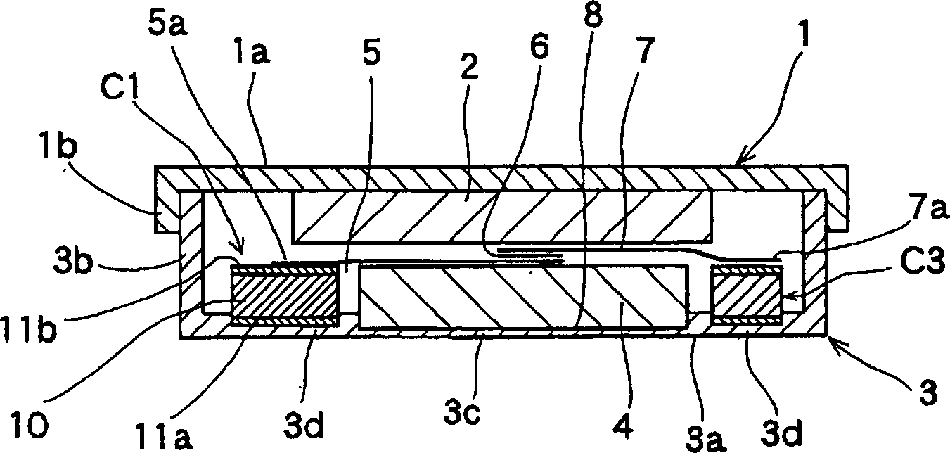
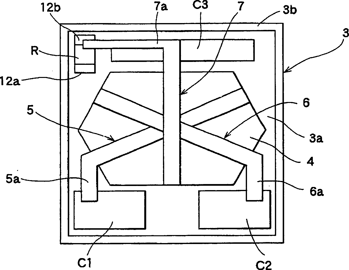
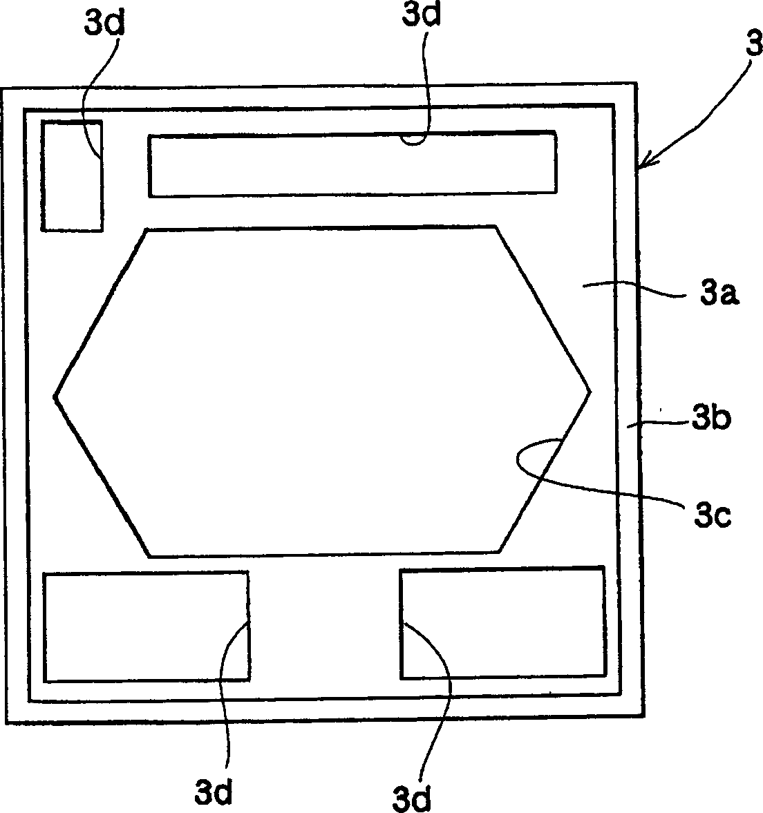
[0022] Referring to the accompanying drawings of the non-reciprocal circuit element of the present invention, there are Figure 1 ~ Figure 4 . in: figure 1 It is a sectional view of the essential parts involved in the non-reciprocal circuit element of the present invention; figure 2 It is a top view showing the non-reciprocal circuit element of the present invention after removing the first yoke and the magnet; image 3 It is a plan view showing the non-reciprocal circuit element of the present invention after removing the second yoke; Figure 4 It is an expanded view of the central conductor involved in the non-reciprocal circuit element of the present invention.

[0023] Below, according to Figure 1 ~ Figure 4 , telling the structure of applying the non-reciprocal circuit element of the present invention in the isolator. The first yoke 1 made of a U-shaped or box-shaped magnetic plate (iron plate, etc.) has a square (rectangular) upper plate 1a and side plates 1b ben...


PUM


Abstract

The invention provides a non-reciprocal circuit element comprising: a ferrite component (4); a first, a second, and a third center conductors (5, 6, 7) arranged at planes sandwiching a dielectric and being different in the vertical direction, wherein a portion of center conductors crosses each other in the vertical direction; a magnet (2) arranged on the center conductors; a first yoke (1) covering the top surface of the magnet (2); and a second yoke (3) for constituting a magnetic closed circuit with the first yoke (1). A first recess (3c) is arranged at the bottom plate (3a) of the second yoke (3), and a lower part of the ferrite component (4) is accommodated in the first recess (3c). According to the accommodation, thinning is attained, and a thin non-reciprocal circuit element is provided. The invention provides a thin, highly productive and inexpensive non-reciprocal circuit element.

Description

technical field [0001] The invention relates to a non-reciprocal circuit element composed of an isolator, a circulator and the like, which is applicable to an antenna duplexer and the like. Background technique [0002] Figure 5 It is a cross-sectional view of a main part of a conventional nonreciprocal circuit element. Below, according to Figure 5 Describe the structure of the prior art non-reciprocal circuit elements. The conventional non-reciprocal circuit element has: a box-shaped first yoke 51, a rectangular plate-shaped magnet 52 arranged in the first yoke 51, a box-shaped second yoke 53 combined with the first yoke 51, and A resin case 54 is mounted in the second yoke 53 and is made of a synthetic resin molding. [0003] In addition, the conventional non-reciprocal circuit element also has: a ferrite magnetic body 55 accommodated in the through hole 54a of the resin case 54, and on the ferrite magnetic body 55, a part becomes Three central conductors 56 formed of...

Claims


Application Information

Patent Timeline
Patent Type & Authority Applications(China)
IPC IPC(8): H01P1/32
Inventor 柴山贵光
Owner ALPS ALPINE CO LTD
Why Eureka
Try Eureka