Annular detecting instrument for concrete gas seepage coefficient and detecting method

A technology of gas permeation and testing methods, which is applied in the direction of instruments, measuring devices, scientific instruments, etc., can solve the problems of complex test procedures, cumbersome experimental operations, laborious loading and unloading, etc., and achieve reliable test results, simple calculation models, and compact equipment.

Active Publication Date: 2006-08-09
SHANGHAI TONGJI CONSTR QUALITY INSPECTION STATION
View PDF0 Cites 27 Cited by
  • Summary
  • Abstract
  • Description
  • Claims
  • Application Information

AI Technical Summary

Problems solved by technology

The test steps are also very strict and the test procedures are complicated
However, this method has the disadvantages that the ex

Method used


Image

  • Annular detecting instrument for concrete gas seepage coefficient and detecting method
  • Annular detecting instrument for concrete gas seepage coefficient and detecting method
  • Annular detecting instrument for concrete gas seepage coefficient and detecting method

Examples


Embodiment 1

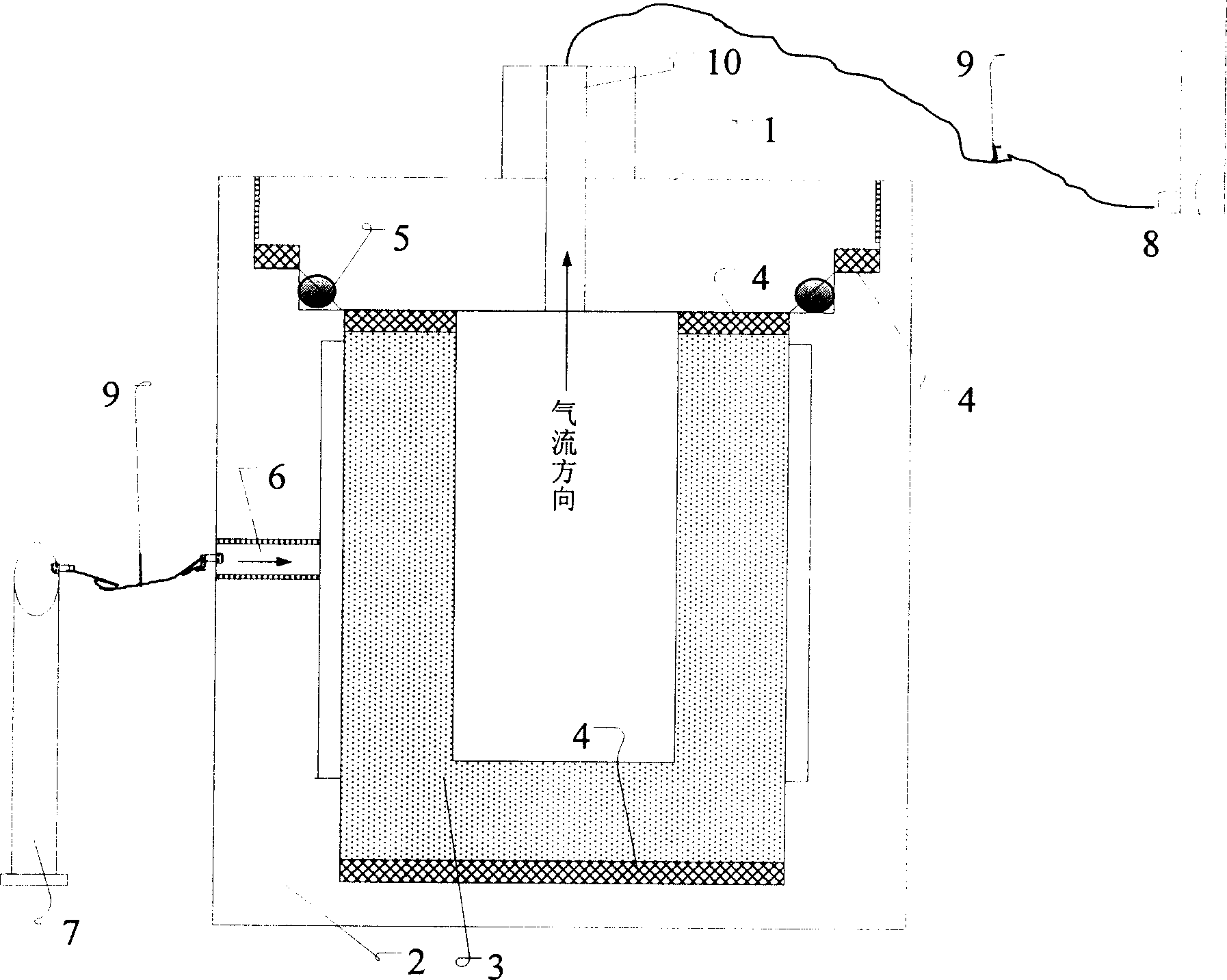
[0029] Embodiment 1: the following parts are pressed figure 1 Those skilled in the art can successfully implement the connection in the manner shown. The cover plate 1 is made of A3 steel material, with a diameter of 220mm on the upper edge and 211mm on the lower edge; the outer shell 2 is made of A3 steel material, with an outer dimension of 236mm in diameter and a total height of 230mm; the size of the tested sample is 200mm in outer diameter, 110mm in inner diameter, The inner cavity is 150mm high and the wall thickness is 45mm; the gasket 4 adopts a 3mm thick vacuum rubber gasket, the gasket 5 adopts an O-shaped rubber gasket of 206×5.30G GB3452.1, and the size of the air inlet 6 is 18mm in diameter; compressed gas The tank 7 is an industrial nitrogen cylinder; the flowmeter 8 is a soap film flowmeter; the hose 9 is a vacuum rubber tube; the hole diameter of the cover plate is 18mm in diameter.

Embodiment 2

[0030] Embodiment 2: test method

[0031] Form the sample according to the mix ratio in Table 1. The specific dimensions are: outer diameter 200mm, inner diameter 110mm, inner cavity height 150mm, wall thickness 45mm.

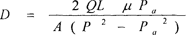
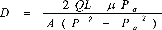
[0032] Dry the above-mentioned concrete samples that have reached the age of 28 days, place them in the casing, tighten the connecting nuts between the casing and the cover plate, open the valve of the compressed gas tank, and feed in N 2 , adjust the air pressure to the specified first pressure value of 0.15MPa, keep the ventilation time in the sample for 20 minutes, start to test the gas flow through the tested sample, and record the flow value; change the test pressure to 0.2MPa and 0.3MPa respectively, Repeat the above test, write down the test values ​​of various conditions, press D = 2 QLμ P a A ...


PUM

PropertyMeasurementUnit
Outer diameteraaaaaaaaaa
The inside diameter ofaaaaaaaaaa
Diameteraaaaaaaaaa

Abstract

Said invention refers to concrete gaseous permeability coefficient annular tester and testing method belonging to concrete material viability detection technique field. It contains cover board, housing, flowmeter, seal ring, and tested sample, wherein cover board housing top, tested sample located in housing with cylindrical form outer wall, inner hollow, toroidal shape cross section, U shape longitudinal section, sealing gasket set in top and bottom of tested sample, one housing side air inlet connected with compressed gas tank, cover board centre with connection porthole, hollow part of tested sample connected with flow instrument through said connection porthole. In testing, tested sample is located in housing, opening compressed gas tank valve, testing sample air permeability, keeping tested sample equilibration time being 10-20 minute, each group tested sample repeating by 3-5 times, changing test pressure and repeat testing, testing tested sample gas flow to obtain tested sample permeability coefficient average value, taking 3-5 tested sample permeability coefficient average value as test value of said group tested sample. Said invention has high accuracy, fine testing repeatability, fine sealed effect, reliable test result, easy and simple to handle etc advantages.

Description

technical field [0001] The invention belongs to the technical field of durability detection of concrete materials, and in particular relates to equipment and a testing method of a concrete gas permeability coefficient annular tester. Background technique [0002] Improving the durability of concrete and prolonging the actual service life of concrete are the focus of the current concrete academic research. The key lies in controlling the permeability of concrete and characterizing the permeability of concrete. According to the penetration medium, there are water and O 2 , N 2 , air, etc., due to the requirements of test speed and low-pressure stability, the research focus is on the steady-state permeability of gases. [0003] The permeability coefficient test methods using gas as the test medium are currently commonly used Figg method and Cembureau method. [0004] The Figg method is a semi-damaged method for measuring the compactness of concrete. During the test, a small h...

Claims


Application Information

Patent Timeline
IPC IPC(8): G01N7/10G01N33/38G01N13/04G06F19/00
Inventor 王中平施惠生李启令
Owner SHANGHAI TONGJI CONSTR QUALITY INSPECTION STATION
Why Eureka
Try Eureka