Air floating unit, carrying method and air floating carrying device
A technology for conveying devices and air, applied in the directions of transportation and packaging, biochemical equipment and methods, conveyors, etc., can solve the problems of increased air consumption, etc. added effect
- Summary
- Abstract
- Description
- Claims
- Application Information
AI Technical Summary
Problems solved by technology
Method used
Image


Examples
no. 1 example
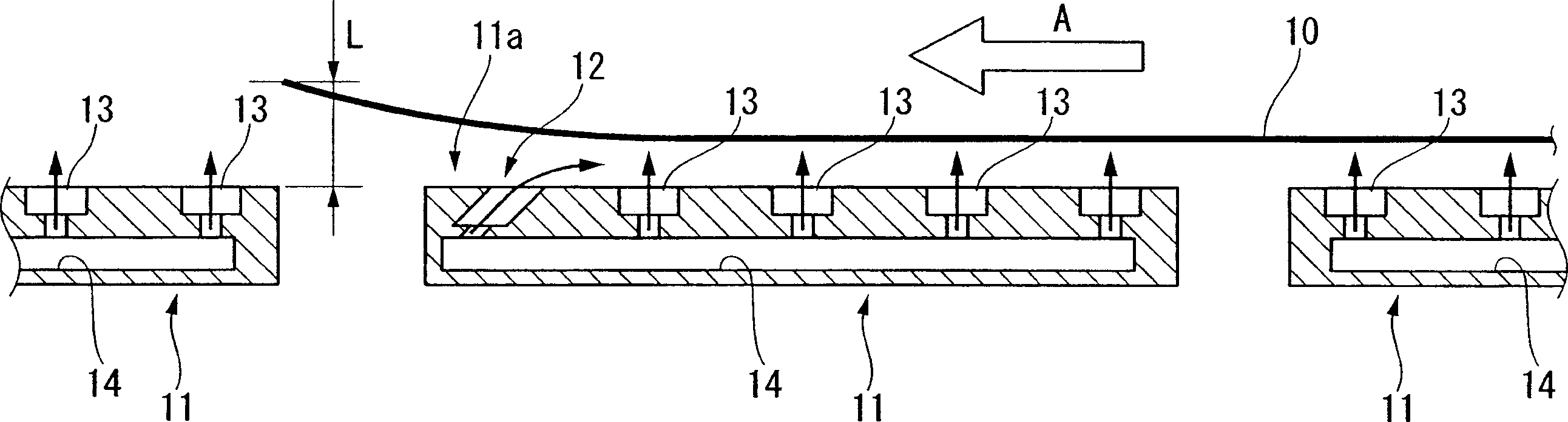
[0032] figure 1 It is explanatory drawing which shows the 1st Example of the air levitation conveyance apparatus of this invention. Here, the air flotation transport device ejects air from the air flotation unit 11 disposed below the planar substrate 10 to float the planar substrate 10 , and transports the planar substrate 10 forward by a delivery mechanism outside the figure. Near the downstream end 11a of the front end of the air floating unit 11 in the direction A is provided a mechanism for increasing the floating amount of the flat substrate 10, that is, an inclined nozzle 12 having a flow component opposite to the transport direction A of the flat substrate 10.
[0033] In this embodiment, the air floating unit 11 has a plurality of vertical nozzles 13 opening upward. Air is collectively supplied from the air supply pipe 14 to the vertical nozzles 13 . In addition, the inclined nozzle 12 provided in the vicinity 11a of the downstream end of the air floating unit 11 is...
no. 2 example
[0036] in addition, figure 2 It is a perspective view which shows the 2nd Example of the air levitation conveyance apparatus of this invention. In this example, if figure 2 As shown, downstream of the air floating unit 21, a mechanism for increasing the floating amount of the planar substrate 10, that is, a separate ejection nozzle 15 is provided. The discharge nozzle 15 discharges air from the downstream end of the air floating unit 21 toward the center.
[0037] In the air-floating conveyor with the above-mentioned structure, the air is also ejected from the downstream end of the air-floating unit 21 toward the central part, and the air flow in the reverse direction A of the flat substrate 10 is blocked, and the reverse direction A is used to prevent the flow of air. The air flow lifts the front end of the planar substrate 10 upward by the amount L. Therefore, even if the rigidity of the planar substrate 10 is low and deflection occurs, or the height adjustment of the a...
no. 3 example
[0039] image 3It is an explanatory diagram showing a third embodiment of the air levitation transport device of the present invention. In this embodiment, the means for increasing the floating amount is the nozzle 30 with a large air ejection amount provided near the downstream end of the air floating unit 31 . The nozzle 30 communicates with the air supply pipe 32 arranged in the air floating unit 31, and ejects air vertically. In addition, the vertical nozzles 13 also communicate with the air supply pipes 32, respectively. In addition, instead of the nozzles 30 having a large amount of air ejection, the arrangement density of the vertical nozzles 13 may be increased to increase the amount of ejected air.
[0040] Next, the amount of air ejected by the air-floating conveyor having the above-mentioned structure is increased at the downstream end of the air-floating unit 31, so that the front end of the planar substrate 10 is lifted upward by the amount L. Therefore, even i...
PUM
 Abstract
Description
Claims
Application Information