
Solar collector

A collection device and sunlight technology, applied in the energy field, can solve the problems of high system cost, no infrared filter, short transmission distance, etc., and achieve the effect of improving collection efficiency, increasing transmission distance, and increasing transmittance

Inactive Publication Date: 2006-08-16
宁波新亚机电有限公司
View PDF0 Cites 4 Cited by
  • Summary
  • Abstract
  • Description
  • Claims
  • Application Information

AI Technical Summary

Problems solved by technology

[0003] Found through literature retrieval to prior art, Zhang Yaoming etc. published " research on the lighting system of gathering sunlight " on " China Engineering Science " volume 4 ninth phase (September 2002), proposed a kind of using phenanthrene The acquisition system composed of Neil lens and plastic optical fiber has the following disadvantages: due to the lack of infrared filter, the lens is small, the light collection efficiency is not high, and the transmission distance is correspondingly short
The article also introduces similar devices at home and abroad. Although other systems at home and abroad use larger lenses to improve collection efficiency, but because there is no infrared filter, too high light energy will burn the plastic optical fiber, so only very Expensive silica fiber for transmission, making the system costly

Method used


Image

  • Solar collector
  • Solar collector

Examples


Embodiment Construction

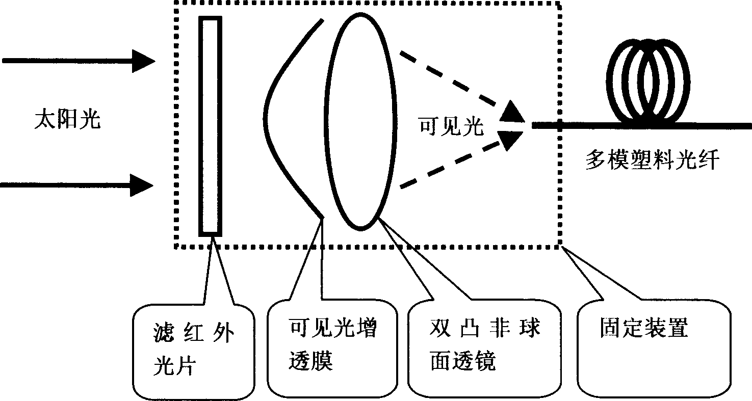
[0011] Such as figure 1 As shown, the present invention comprises: infrared filter, visible light anti-reflection film, double-convex aspheric lens and fixing device, and visible light anti-reflection film is plated on the double-convex aspheric lens, and fixing device is infrared filter, double-convex aspheric lens The spherical lens (both sides are coated with visible light anti-reflection coating) and the optical fiber are firmly fixed. The infrared filter is located in front of the double-convex aspheric lens, and the optical fiber is located at the focus of the double-convex aspheric lens.

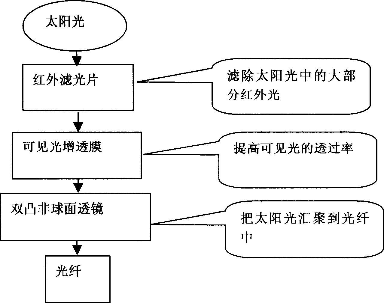
[0012] In the present invention, the sunlight first passes through an infrared filter, and the device filters out most of the infrared light in the sunlight; then the sunlight passes through a visible light anti-reflection coating, which is coated on the surface of a biconvex aspheric lens, Here the transmittance of visible light will be strengthened; then through the biconvex aspher...


PUM


Abstract

A sunlight collector comprises an infrared filter, a visible light anti-reflection film, a lenticular non-spherical lens and a fixing device. The visible light anti-reflection film is coated on the lenticular non-spherical lens. The infrared filter, the lenticular non-spherical lens and the optical fiber are firm jointed via the fixing device. The infrared filter is located in front of the lenticular non-spherical lens. The optical fiber is located in the focal place of the lenticular non-spherical lens. The sunlight first goes through the infrared filter to filter the most infrared light in the sunlight, and then goes through the visible spectral transmission film to strengthen the transmissivity of the visible light, at last goes through the lenticular non-spherical lens acting for collecting the sunlight, the collected sunlight goes to the optical fiber to be transmitted.

Description

technical field [0001] The present invention relates to a device in the field of energy technology, in particular to a sunlight collection device. Background technique [0002] In our country, such economically developed cities with strong demand for lighting are often located in power-deficient areas, and the power supply is tight; moreover, electric energy is a secondary energy source. Most of the electric energy in our country is generated by coal, natural gas, nuclear energy and other non-renewable resources. The power generation process often inevitably produces various environmental pollutants. However, sunlight is the most typical and most energetic natural light source, which is inexhaustible and inexhaustible. But so far, most of people's utilization of sunlight stays in using a small part of sunlight to shoot indoors through glass windows and skylights to achieve the effects of lighting and landscape. This method is limited by the design and structure of the buil...

Claims


Application Information

Patent Timeline
IPC IPC(8): F24J2/00
CPCY02E10/40
Inventor 李长治姜文宁陈建平罗新良
Owner 宁波新亚机电有限公司
Learn More