
Laminate with fill layer

A filler layer and plastic technology, applied in layered products, thin material processing, metal layered products, etc., can solve problems such as unevenness of laminates

Active Publication Date: 2006-08-16
FOKKER AEROSTRUCTURES
View PDF0 Cites 5 Cited by
  • Summary
  • Abstract
  • Description
  • Claims
  • Application Information

AI Technical Summary

Problems solved by technology

As a result of partial overlapping of the metal layers, the laminates have inhomogeneities, which can in some cases lead to adverse consequences

Method used


Image

  • Laminate with fill layer
  • Laminate with fill layer

Examples


Embodiment Construction

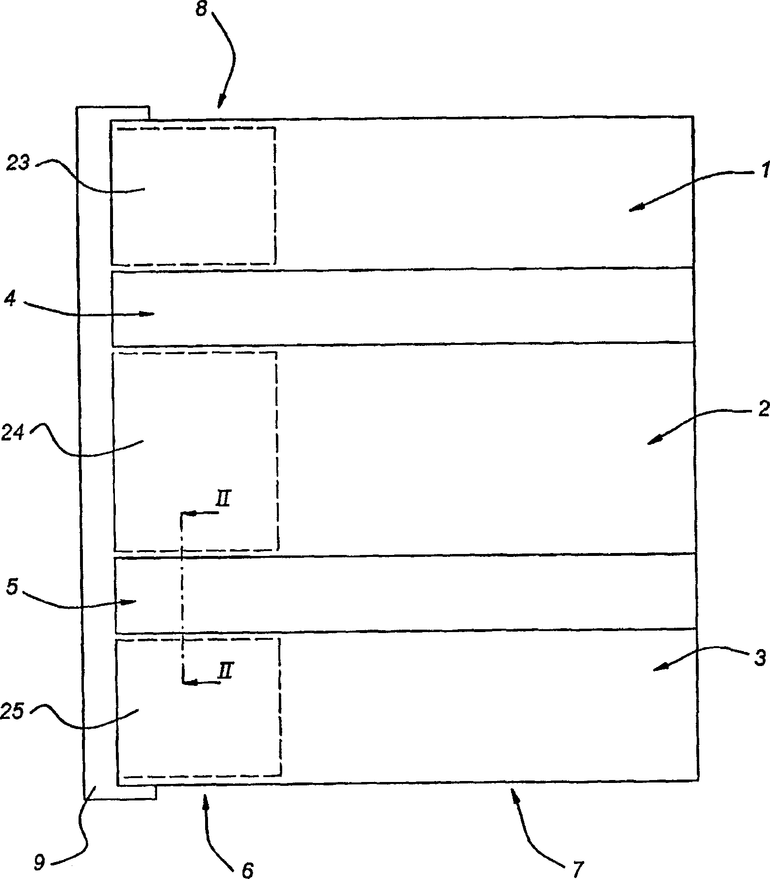
[0010] figure 1 The laminate shown in comprises three laminate parts 1 , 2 and 3 which are fastened to each other by means of joints 4 , 5 . In addition, two distinct regions can be distinguished in the laminate, namely the region 6 provided with a fill, generally indicated by reference numeral 8, between the layers of the laminate, and the region without a fill , in other words the standard laminate 7. At the location of the area 6 the ply can be secured to another ply by means of strip frames 9 .

[0011] It is known that at the position of the combination 4 , 5 the thickness of the standard laminates is somewhat greater since the edges of the laminates overlap one another here. This means that at least one side of the laminate is not flat but somewhat stepped. In some applications, this is not ideal. For example, in the case of aircraft skins, it is preferred that the sides of the laminate be completely flat. The frame 9 can be connected to one side, the inner side, wh...


PUM


Abstract

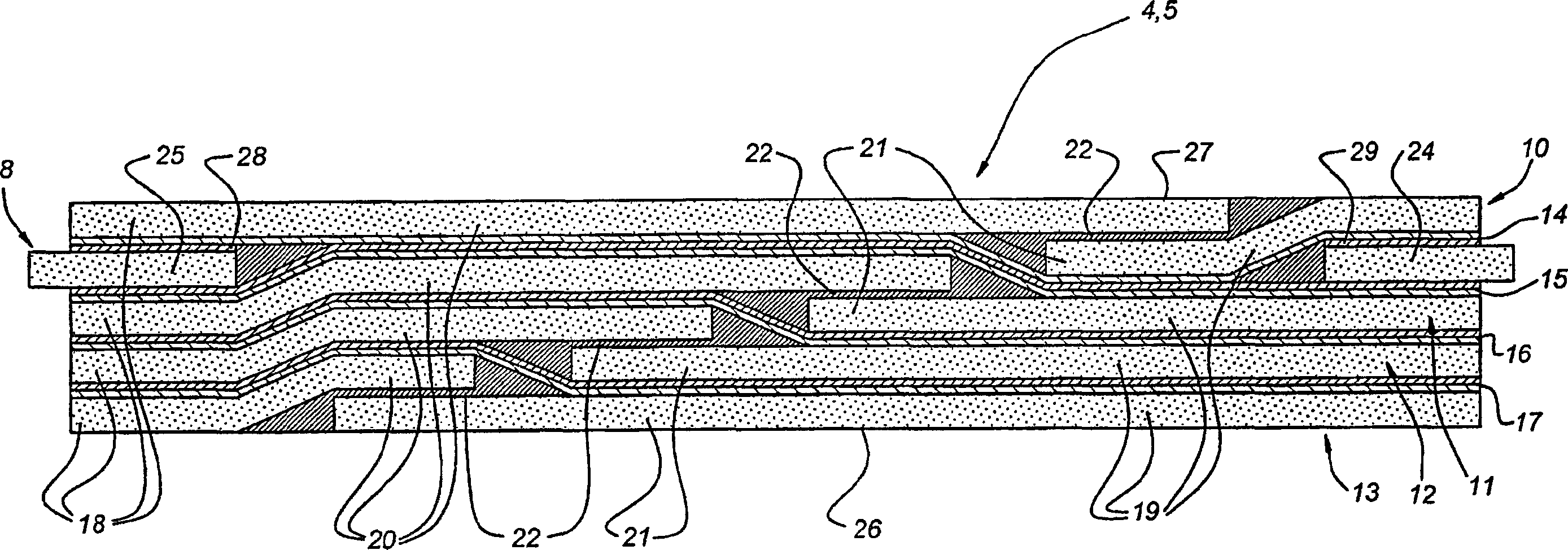
A laminate consisting of alternately offset metal layers and at least one plastic bonding layer, each metal layer comprising at least two metal layer portions having overlapping edges bonded to each other. In order to make the different parts uniform in thickness, a filler layer is provided, which has a thickness such that, at the location of the filler layer, the thickness of the laminate is equal to the thickness at the location of the overlapping edge.

Description

technical field [0001] The invention relates to a laminate consisting of alternately displaced metal layers and at least one plastic bonding layer, wherein each metal layer respectively comprises two metal layer parts having mutually overlapping edge. Background technique [0002] Such laminates are well known. The laminate may be a laminate in which the metal layers are bonded to each other by an adhesive layer; or a laminate with one or more fiber layers impregnated with an adhesive between the metal layers. As a result of the partial overlapping of the metal layers, the laminates have inhomogeneities, which can in some cases lead to disadvantageous consequences. If such laminates are secured to a structural member, such as a frame, one metal layer portion must be spliced ​​to ensure that both metal layer portions are in direct contact with the frame. In the case of aircraft skins, this means that the outside of the skin also has a seam which is not aerodynamically idea...

Claims


Application Information

Patent Timeline
Patent Type & Authority Applications(China)
IPC IPC(8): B29C70/88B32B15/08B32B3/08B32B3/10B32B15/14
CPCY10T428/24752B29C70/885Y10T428/17Y10T428/24Y10T428/195B32B15/08Y10T428/24322B32B3/08Y10T428/192B32B15/14Y10T428/19Y10T428/12444B32B3/10B32B2260/021B32B7/12B32B15/043
Inventor 阿卜杜勒·法兹尔·拉贾巴利威廉·扬尼古拉斯·特尔·施特格
Owner FOKKER AEROSTRUCTURES
Learn More