Recovering and utilizing device for rain in factory area

A technology of rainwater collection and rainwater, which is applied to the configuration of water supply devices, drinking water devices, and water supply pools, to achieve the effects of saving consumption, improving environmental protection standards, and alleviating water resource scarcity

Inactive Publication Date: 2006-08-23
GUIYANG AL-MG DESIGN & RES INST
View PDF0 Cites 4 Cited by
  • Summary
  • Abstract
  • Description
  • Claims
  • Application Information

AI Technical Summary

Problems solved by technology

The present invention aims to provide a device, so that the drainage of the factory will not pollute the nearby

Method used


Image

  • Recovering and utilizing device for rain in factory area

Examples


Embodiment Construction

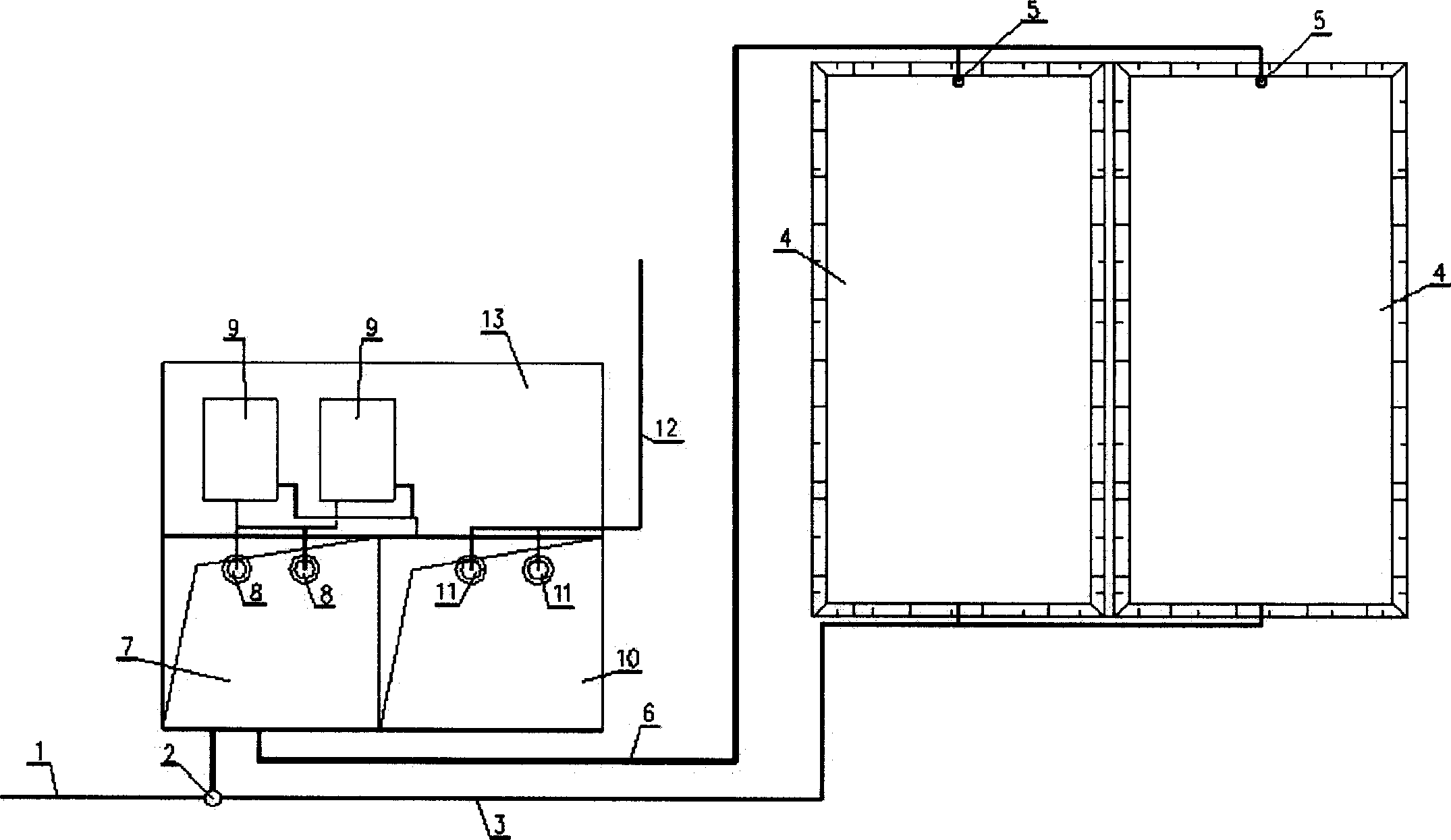
[0009] Embodiments of the present invention: as figure 1 As shown, the interception well 2, the regulating pool 7, the reuse pool 10, the sewage treatment room 13, and the sewage treatment room 13 are installed with wastewater treatment equipment 9 in the factory. The multiple is 2 to 3; a sedimentation tank 4 is set outside the factory, and its volume is determined according to the local rainfall and evaporation. The amount of evaporated water on the surface of the sedimentation tank for one year. Anti-leakage measures should be set for the settling tank; production wastewater and rainwater collection pipes 1 are buried in the factory area, and the production wastewater and rainwater collection pipes 1 are connected to the interception well 2 and to the regulating pool 7; one end of the rain drainage pipe is connected to the interception well 2 Connect, the other end is connected with the settling tank 4; Install the rainwater return water lifting pump 5 in the settling tank...


PUM


Abstract

The rain water recovering and utilizing apparatus for factory area includes production waste water and rain water collecting pipeline connected through regulating water pond to the rain water draining pipeline, deposit tank connected to the rain water draining pipeline, rain water backing and lifting pump inside the deposit tank, rain water backing pipeline with one end connected to the rain water backing and lifting pump and the other end connected to the regulating water pond, the lifting pump in the regulating water pond and connected to the waste water treating unit, and back water pump in the water backing pond and connected to the back water pipeline. The present invention is especially suitable for where water resource is lacked and there is relatively high environment protection requirement.

Description

Technical field: [0001] The invention relates to a rainwater recycling device in a factory area. Background technique: [0002] At present, there are two ways to configure the rain drainage system in the factory. One is to set up the rain drainage system separately and discharge the collected rainwater directly to nearby rivers or lakes; the other is to combine the rain drainage system with production or domestic drainage. The system is jointly built, and interception wells are set at the end of the pipe network, and the production or domestic sewage and the intercepted initial rainwater are sent to the sewage treatment station for treatment. Most of the rainwater and the sewage and waste water mixed in the rainwater are directly discharged to nearby rivers or lake. For the first method, all the sewage and waste water are sent to the sewage treatment station for treatment, which will not pollute the nearby rivers or lakes, but the initial rainwater also contains certain pol...

Claims


Application Information

Patent Timeline
IPC IPC(8): E03B3/02E03B11/02
CPCY02A20/00Y02A20/108
Inventor 李永升
Owner GUIYANG AL-MG DESIGN & RES INST
Why Eureka
Try Eureka