Environment-friendly ice making integrated machine

An all-in-one, environmentally friendly technology, used in ice manufacturing, refrigerators, leisure ice making, etc., can solve the problems of inconvenient transportation, installation and use, large size of the ice machine, and inability to reduce the size, etc., to achieve a compact and convenient structure. The effect of transportation and ease of transportation

Pending Publication Date: 2017-09-05
魏一伦
View PDF8 Cites 0 Cited by
  • Summary
  • Abstract
  • Description
  • Claims
  • Application Information

AI Technical Summary

Problems solved by technology

[0003] The ice machine in the prior art includes a lot of equipment, usually including a compressor, a high-pressure tank (oil separator), a low-pressure tank (refrigerant storage), a liquid pump and other equipment, plus many connected refrigerant delivery pipes , causing the ice machine to be bulky and complex in structure
[0004] During the transportation of the ice machine, these devices need to be packaged separately. During the installation of the ice machine, these devices also need to be installed separately, and finally connected with pipes, which is not convenient for transportation, installation and use, and cannot be reduced in size. After that, it occupies a large area

Method used


Image

  • Environment-friendly ice making integrated machine
  • Environment-friendly ice making integrated machine
  • Environment-friendly ice making integrated machine

Examples


Embodiment 1

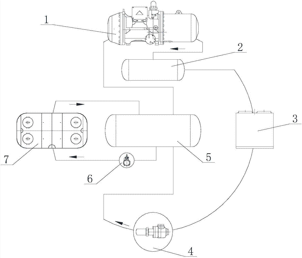
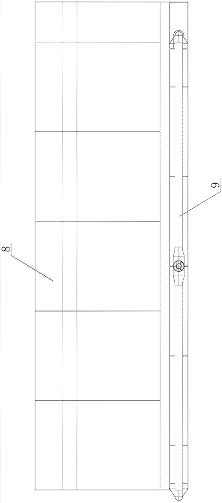
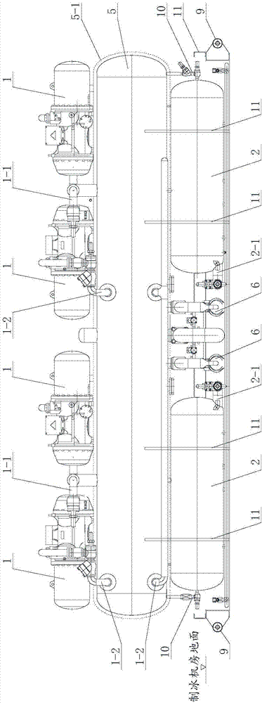
[0047] Such as figure 1 , figure 2 , image 3 , Figure 4 Shown is an embodiment of the present invention. In this embodiment, the environmental protection integrated ice making machine includes a compressor 1, an oil separator 2 and a low-pressure circulation tank 5. The compressor 1, an oil separator 2 and a low-pressure circulation tank 5 pass refrigerant The conveying pipelines are connected in sequence, the oil separator 2 is located in the lower layer, the low-pressure circulation tank 5 is located in the middle layer, and the compressor 1 is located in the upper layer.

[0048] Such as image 3 , Figure 4 As shown, the width and length of the low-pressure circulation tank 5 completely absorb the width and length of the compressor 1 and the oil separator 2.

[0049] Through such a laminated design structure, the main components of the environmental protection ice-making integrated machine can be combined, the space of the unit can be fully utilized, the structure is compact,...

Embodiment 2

[0075] In this embodiment, the difference from embodiment 1 is that Figure 7 As shown, the throttle valve group 10 is provided with a parallel main path and a secondary path along the refrigerant conveying direction, and the main path is sequentially provided with a check valve 10-9, a filter 10-8, and an electronic throttle valve 10- 7 and the first shut-off valve 10-6, the inlet of the check valve 10-9 is the refrigerant inlet, and the outlet of the first shut-off valve 10-6 is the refrigerant outlet.

[0076] Such as Figure 7 As shown, the secondary path and the main path share the check valve 10-9, which also starts from the check valve 10-9, followed by the mechanical throttle valve 10-1, the refrigerant charging port 10-2 and the second stop The outlet of the valve 10-3 and the second stop valve 10-3 is the outlet of the refrigerant. A check valve can also be installed at the refrigerant charge port 10-2.

[0077] The primary path and the secondary path do not need to be o...

Embodiment 3

[0083] In this embodiment, as Picture 11 As shown, the inside of the oil separator 2 (high pressure tank) is divided into an oil and gas separation chamber 2-3 and a liquid storage tank 2-6. The refrigerant returning from the condenser 3 is first delivered to the liquid storage tank 2-6, and then passed through the throttle The valve group 10 is delivered to the low-pressure circulation tank 5.

[0084] Because the refrigerant returning from the condenser 3 may be in a gas-liquid mixed state, by designing such a high-pressure tank structure, on the one hand, the gas-liquid mixed refrigerant returning from the condenser 3 can be adjusted in the liquid storage tank 2-6. Let the liquid refrigerant be delivered to the throttle valve group 10, because the liquid refrigerant has a better throttling and pressure regulation effect. On the other hand, the high-pressure tank can be reasonably developed and utilized to make full use of the unit space and reduce the unit volume.

[0085] A h...


PUM


Abstract

The invention discloses an environment-friendly ice making integrated machine. The technical problems that an ice making machine is large in size, complicated in structure and inconvenient to transport, install and use in the prior art are solved. The environment-friendly ice making integrated machine comprises a compressor, an oil separator and a low-pressure circulating tank. The compressor, the oil separator and the low-pressure circulating tank are connected in sequence through a refrigerant transporting pipeline. The oil separator is located in the lower layer. The low-pressure circulating tank is located in the middle layer. The compressor is located in the upper layer. According to the environment-friendly ice making integrated machine, the structural relationship between the devices is fully optimized; the main devices are combined together; the unit space is fully utilized; the structure is compact; the unit size is reduced; and the environment-friendly ice making integrated machine is convenient to transport, install and use.

Description

Technical field [0001] The invention relates to an environmental protection ice-making integrated machine, which is used for making ice for sports facilities on ice, and can also refrigerate equipment or places such as large-scale cold chain transportation equipment, low-temperature central air-conditioning, and large-scale computer rooms. Background technique [0002] Ice skating rinks, ice hockey arenas, curling arenas and other places to make ice, large-scale cold chain transportation equipment, low-temperature central air-conditioning, large-scale computer rooms and other equipment or places for refrigeration, all require ice machines. [0003] The ice maker in the prior art includes a lot of equipment, usually including compressors, high-pressure tanks (oil separators), low-pressure tanks (refrigerant storage), liquid pumps and other equipment, plus many connected refrigerant pipelines , Resulting in a large volume and a complex structure of the ice maker. [0004] In the proce...

Claims


Application Information

Patent Timeline
Patent Type & Authority Applications(China)
IPC IPC(8): F25B41/00F25B31/00F25C3/02F25B41/40
CPCF25B31/00F25B41/00F25C3/02
Inventor 佟伟魏一伦
Owner 魏一伦
Why Eureka
Try Eureka