Telescopic shaft
A telescopic shaft, female shaft technology, applied in the directions of shafts, bearings, couplings, etc., can solve the problems of stick-slip, inability to perform smooth sliding motion, etc., and achieve the effect of smooth sliding and minimizing deterioration.
- Summary
- Abstract
- Description
- Claims
- Application Information
AI Technical Summary
Problems solved by technology
Method used
Image
Examples
no. 1 example
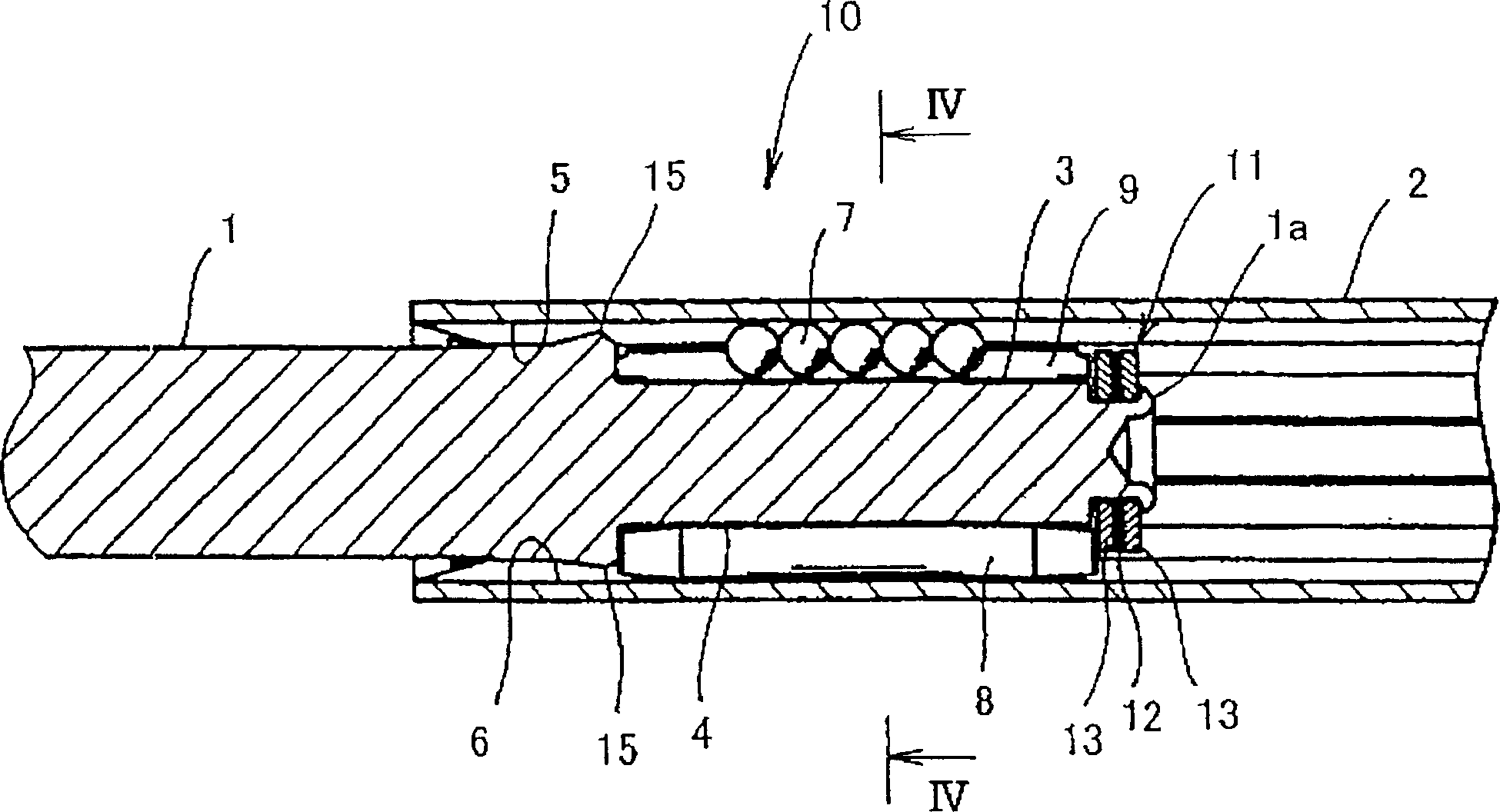
[0088] figure 2 It is a longitudinal sectional view of the first embodiment of the vehicle steering telescopic shaft of the present invention.
[0089] image 3 It is a longitudinal sectional view of the first embodiment of the vehicle steering telescopic shaft of the present invention.
[0090] Figure 4 is along image 3 A transverse cross-sectional view taken along line IV-IV.
[0091] Such as figure 2 and 3 As shown, the telescopic shaft 10 includes a male shaft 1 and a female shaft 2, and the two shafts are slidably fitted together in a manner to prevent relative rotation to each other. Universal joints UJ are connected to male shaft 1 and female shaft 2 respectively.
[0092] Such as Figure 4 As shown, three axial grooves 3 are formed in the outer peripheral surface of the male shaft 1, and the three axial grooves are circumferentially spaced from each other at an angle of 120 degrees. Similarly, three axial grooves 5 are formed extending in the inner periphe...
no. 2 example
[0141] Figure 5A shows a second embodiment of the invention and is along image 3 A transverse cross-sectional view taken along line IV-IV. Figure 5B is an enlarged cross-sectional view showing a part of the outer surface of the columnar member.
[0142] In this embodiment, the inner peripheral surface of the female shaft 2 is subjected to surface hardening treatment, and thus the hard layer Ha is formed, as described in the above-mentioned first embodiment. It is not always necessary to subject the entire inner peripheral surface of the female shaft 2 to surface hardening treatment, but at least the inner surface of the axial groove 6 in contact with each needle roller (cylindrical member) 8 may be subject to surface hardening treatment, and the surface hardening treatment also Heat treatment may be applied to the surface of each column member 8, thereby forming the hard layer Hb thereon.
[0143]In addition to the hard layer Hb (a hard layer formed by surface hardening ...
no. 3 example
[0146] In the present embodiment, surface hardening treatment is applied on the inner peripheral surface of the female shaft 2, thereby forming the hard layer Ha, as described in the above first embodiment. It is not always necessary to subject the entire inner peripheral surface of the female shaft 2 to surface hardening treatment, but at least the inner surface of the axial groove 6 in contact with each needle roller (cylindrical member) 8 may be subject to surface hardening treatment, and the surface hardening treatment also Applicable to the inner surface of the axial groove 5 which is in contact with each row of rolling balls 7 . Surface hardening treatment may also be applied to the surface of each columnar member 8 by heat treatment, thereby forming a hard layer Hb thereon.
[0147] In addition to the hard layer Ha (a hard layer formed by surface hardening treatment, and its surface hardness is not less than Hv 400), the inner surface of each axial groove 6 on the femal...
PUM
| Property | Measurement | Unit |
|---|---|---|
| hardness | aaaaa | aaaaa |
| hardness | aaaaa | aaaaa |
| thickness | aaaaa | aaaaa |
Abstract
Description
Claims
Application Information
 - R&D
- Intellectual Property
- Life Sciences
- Materials
- Tech Scout
- Unparalleled Data Quality
- Higher Quality Content
- 60% Fewer Hallucinations
Browse by: Latest US Patents, China's latest patents, Technical Efficacy Thesaurus, Application Domain, Technology Topic, Popular Technical Reports.
© 2025 PatSnap. All rights reserved.Legal|Privacy policy|Modern Slavery Act Transparency Statement|Sitemap|About US| Contact US: help@patsnap.com


