Transmission

A technology of transmission and lubrication mechanism, applied in the direction of toothed elements, gear lubrication/cooling, belt/chain/gear, etc., can solve problems such as material cost or assembler increase, reduction of lubricating oil supply efficiency, and layout space limitation. , to achieve the effect of improving oil supply efficiency, light weight and small layout space

Active Publication Date: 2006-08-30
AISIN AI CO LTD +1
View PDF2 Cites 15 Cited by
  • Summary
  • Abstract
  • Description
  • Claims
  • Application Information

AI Technical Summary

Problems solved by technology

In this case, the oil reservoir is formed by utilizing a closed space near one end of the shaft, and lubricating oil may sometimes leak from a gap between parts forming the oil reservoir, which may reduce the supply of lubricating oil s efficiency
Also, separate oil receivers and oil reservoirs may be required when there are several machine parts to be supplied with lubricating oil
In this case, various problems may arise such as an increase in weight due to an increase in the number of parts, a limitation in arrangement space, an increase in material cost or assemblers

Method used


Image

  • Transmission
  • Transmission
  • Transmission

Examples


Embodiment Construction

[0024] Embodiments of the present invention will be described in detail below with reference to the accompanying drawings.

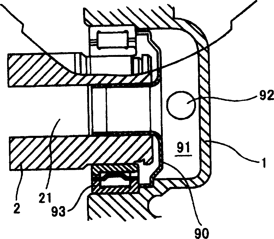
[0025] exist figure 1 The bearing part of the existing transmission and the vicinity of the input shaft 2 are enlarged in the figure. Usually, such as figure 1 As shown, the oil reservoir 91 is formed by a wall 90 coupled near the axial end of the input shaft 2 and separated from the transmission case 1 by a space. Lubricating oil as lubricant is collected by a pan (not shown), and supplied into the oil reservoir 91 through the oil supply port 92 . Then, lubricating oil is supplied to the axial oil passage 21 inside the input shaft 2 . However, in this lubricating structure, lubricating oil leaks from the gap between the wall 90 and the transmission case 1, and / or leaks from the gap between the bearing portion 93 and the transmission case 1, resulting in sometimes reduced oil supply efficiency.

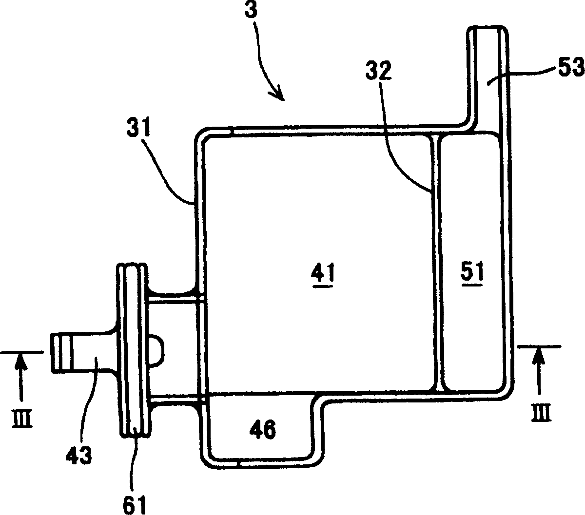
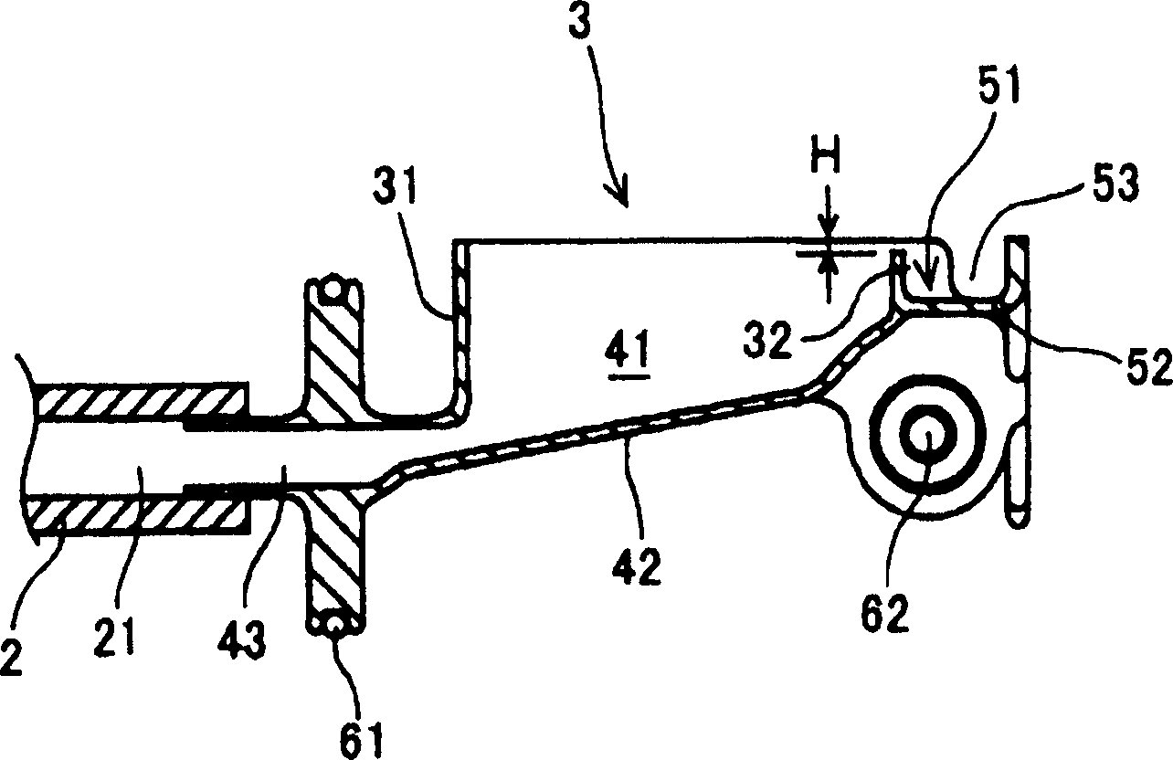
[0026] like figure 2 and 3 As shown, the transmissi...


PUM


Abstract

A transmission includes: a casing of the transmission; a shaft rotatably supported by the casing and having an oil passage; plural gears mounted on the shaft. The lubricant is partly lifted and stirred in response to a shift operation implemented by selectively engaging and rotating the gears. The transmission further includes a lubricating mechanism placed at a position higher than the shaft and having an upper end opening in an upward direction so as to collect and store the lifted lubricant. The lubricating mechanism is provided with an oil supply port through which the lubricant is guided to the oil passage of the shaft.

Description

technical field [0001] The present invention generally relates to a transmission for a vehicle. More particularly, the present invention relates to a lubrication mechanism for use in a vehicle transmission. Background technique [0002] Vehicles driven by driving power sources such as an internal combustion engine and a motor as non-limiting examples each have a transmission specifically for generating a vehicle speed and driving power corresponding to road conditions. In such a transmission, a plurality of gears mounted on an input shaft and an output shaft are operatively selected and meshed with the gears so that driving force is transmitted at predetermined gear ratios designed for respective gears. Such transmissions typically have a lubricating mechanism configured to store and circulate lubricant in the transmission to facilitate lubrication of the gear meshing and sliding parts and to inhibit variator drop, which may be due to friction of. [0003] In order to per...

Claims


Application Information

Patent Timeline
Patent Type & Authority Applications(China)
IPC IPC(8): F16H57/04F16H57/02
CPCF16H57/043F16H57/0426F16H57/045F16H57/0471Y10T74/2186
Inventor 宇佐美诚司山田贵文新田康博池田晓彦小川真治
Owner AISIN AI CO LTD
Why Eureka
Try Eureka