
Double face display panel

A double-sided display and panel technology, applied in lighting devices, optics, light sources, etc., can solve the problems of limited or insufficient brightness of the double-sided display panel body, and difficult reduction in volume

Inactive Publication Date: 2006-08-30
AU OPTRONICS CORP
View PDF0 Cites 2 Cited by
  • Summary
  • Abstract
  • Description
  • Claims
  • Application Information

AI Technical Summary

Problems solved by technology

[0008] Another purpose of the present invention is to improve the disadvantages of existing double-sided display panel components, which are difficult to reduce in volume.
[0009] Another object of the present invention is to improve the shortcomings of the existing double-sided display panel body of limited or insufficient brightness

Method used

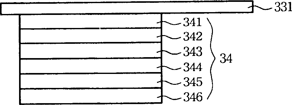

Image

  • Double face display panel
  • Double face display panel
  • Double face display panel

Examples


Embodiment Construction

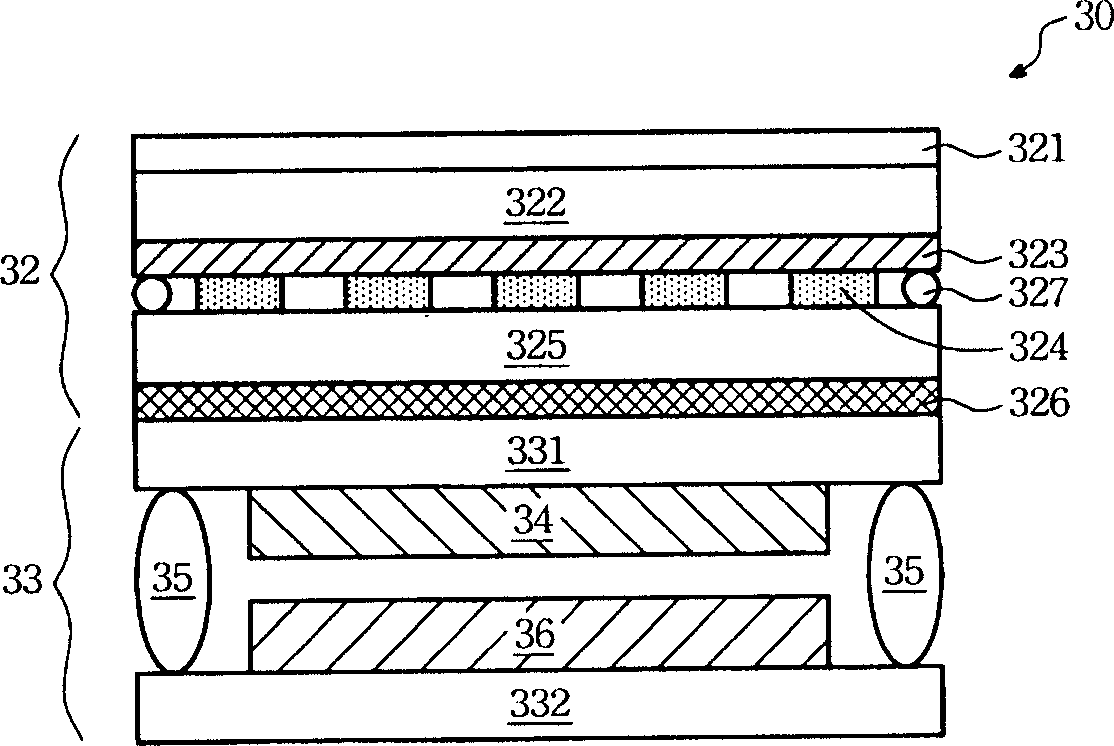
[0038] Please refer to figure 2 , figure 2 It is a schematic side sectional view of the double-sided display panel of the present invention. The double-sided display panel 30 includes a liquid crystal panel 32 , a first electroluminescent structure 34 and a second electroluminescent structure 36 . The first electroluminescence structure 34 is disposed below the liquid crystal panel 32 and provides a backlight for the liquid crystal panel 32 upward. Through the first electroluminescence structure 34 , the liquid crystal panel 32 can display images upward. The second electroluminescent structure 36 is disposed under the first electroluminescent structure 34 and displays images downward.

[0039] Liquid crystal panel 32 comprises upper polarizer 321, upper glass 322, color filter 323, liquid crystal layer 324, lower glass 325 and lower polarizer 326 from top to bottom, and between upper glass 322 and lower glass 325 there is The sealant 327 surrounds the liquid crystal laye...


PUM


Abstract

The invention relates to a double side display panel that includes liquid crystal panel, a first electric laser light structure that is set under liquid crystal panel to supply backlight for liquid crystal panel, and a first electric laser light structure set under the first electric laser light structure to display the image.

Description

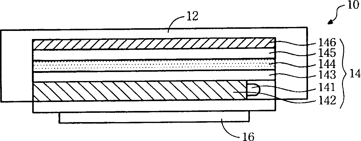
technical field [0001] The present invention relates to a display panel, in particular to a display panel capable of displaying images on both sides. Background technique [0002] Double-sided display panels are currently mostly used in some portable electronic products, for example, the inner and outer screens of some mobile phones are applications of double-sided display panels. Please refer to figure 1 , which is a schematic side sectional view of a conventional double-sided display panel. The double-sided display panel 10 includes a liquid crystal panel 12 , a backlight module 14 , and an organic electroluminescent panel (OLED panel) 16 . The backlight module 14 provides a backlight for the liquid crystal panel 12 , so that the liquid crystal panel 12 faces upward to display images. The organic electroluminescent panel 16 faces downward to display images. [0003] Since it is mostly used in portable electronic products, the size of the double-sided display panel 10 i...

Claims


Application Information

Patent Timeline
Patent Type & Authority Applications(China)
IPC IPC(8): G02F1/13H05B33/00G09F9/00
Inventor 宋锦忠杨文坪
Owner AU OPTRONICS CORP
Learn More