Early effect cancelling circuit, differential amplifier, linear regulator, and early effect canceling method

A technology of differential amplifiers and elimination circuits, applied in amplifiers, amplifiers with semiconductor devices/discharge tubes, instruments, etc.

Active Publication Date: 2006-08-30
CYPRESS SEMICON CORP
View PDF1 Cites 4 Cited by
  • Summary
  • Abstract
  • Description
  • Claims
  • Application Information

AI Technical Summary

Problems solved by technology

If the input and output voltage ratio is small, the efficiency of the linear regulator is sufficient for practical applications

Method used


Image

  • Early effect cancelling circuit, differential amplifier, linear regulator, and early effect canceling method
  • Early effect cancelling circuit, differential amplifier, linear regulator, and early effect canceling method
  • Early effect cancelling circuit, differential amplifier, linear regulator, and early effect canceling method

Examples


Embodiment Construction

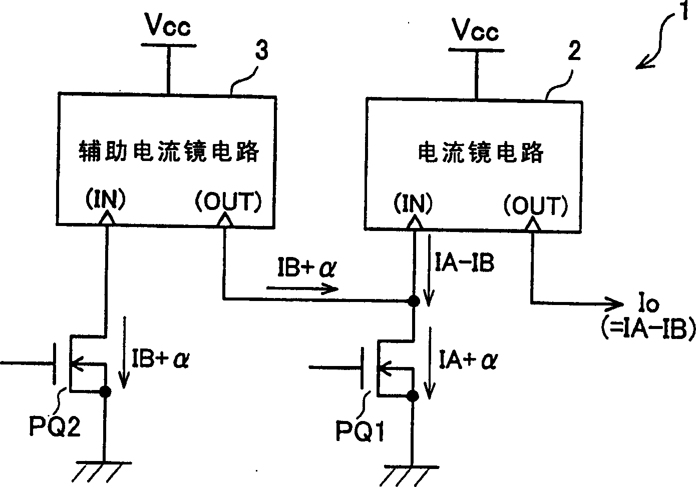
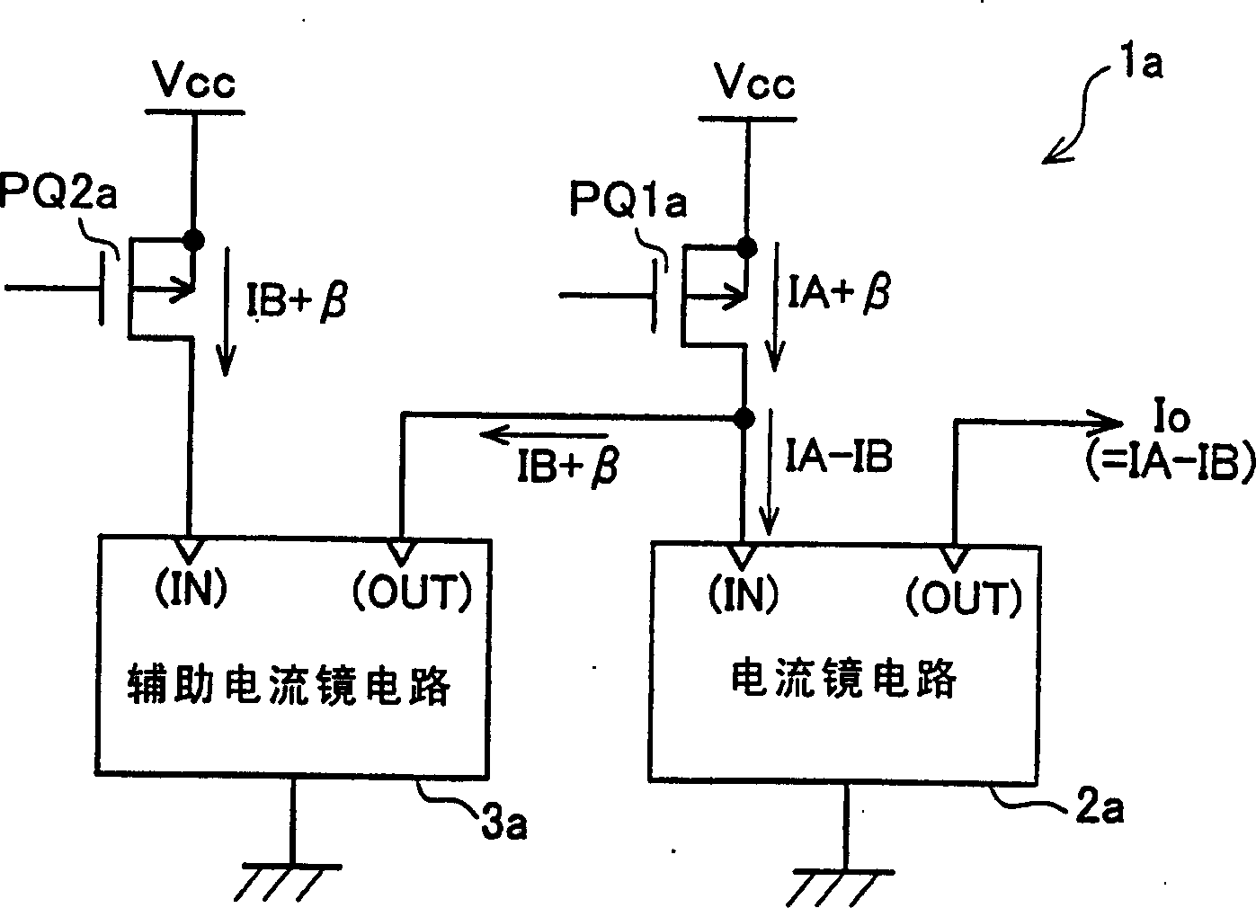
[0025] Refer to below Figure 1 to Figure 6 Let's specifically explain specific embodiments of the Allais effect cancellation circuit, differential amplifier, linear regulator, and Allais effect cancellation method. figure 1 with figure 2 The principle diagram of the present invention is shown in.

[0026] figure 1 The Allai effect cancellation circuit 1 is shown. The Allais effect cancellation circuit 1 includes a current mirror circuit 2, an auxiliary current mirror circuit 3, and input transistors PQ1 and PQ2. The current mirror circuit 2 and the auxiliary current mirror circuit 3 are the same in connection and configuration. The input transistors PQ1 and PQ2 are the same in connection and configuration. The output terminal of the auxiliary current mirror 3 is connected to the input terminal of the current mirror circuit 2. The auxiliary current mirror circuit 3 is connected in parallel with the current mirror circuit 2. The output current of the auxiliary current mirror ci...


PUM


Abstract

In an input transistor of current mirror circuit, it is intended to prevent the current generated by Early effects from appearing in the output current of the current mirror circuit. Having an Early voltage detector 22 of same connection and structure as a driver circuit 21 , and connected in parallel to the driver circuit 21 , the current flowing in input transistor Q 9 of the Early voltage detector 22 is detected. Output current (current IQ 11 ) of Early voltage detector 22 is added to input current (current IQ 5 ) of driver circuit 21 . As a result, in input current (current IQ 7 ) of current mirror circuit 25 , current alpha due to Early voltage effects can be canceled. At the same time, current alpha due to Early voltage effects generated in input transistor Q 5 of current mirror circuit 25 is prevented from appearing in output current (current IQ 8 ) of current mirror circuit 25.

Description

Technical field [0001] The present invention relates to an Allai effect elimination circuit and an Allai effect elimination method, and more particularly, to a circuit and method capable of preventing the current generated by the Allai effect from appearing in the output current of a current mirror circuit. Background technique [0002] If the input current flowing into the current mirror circuit contains a current change component caused by the Early effect, the effect will directly appear in the output current of the current mirror circuit. Therefore, as an example used in a DC-DC converter of a linear regulator system, the current mirror circuit is explained. [0003] In laptops and other portable appliances, the battery is used as the power source of the appliance, but the battery voltage usually drops with the progress of the discharge, and the DC-DC converter is used to try to stabilize the battery output voltage to maintain the power of the appliance. The voltage used is c...

Claims


Application Information

Patent Timeline
Patent Type & Authority Applications(China)
IPC IPC(8): G05F3/24G05F3/26
CPCH03F2200/303G05F1/575H03F3/45273H03F3/345H03F2200/91
Inventor 木崎贵洋安河内克之伊藤秀信
Owner CYPRESS SEMICON CORP
Why Eureka
Try Eureka