[0038] The present invention will be further described below in conjunction with the drawings and embodiments.
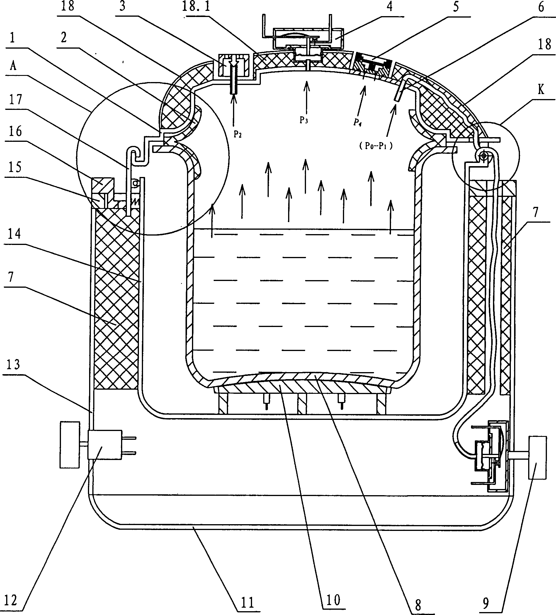
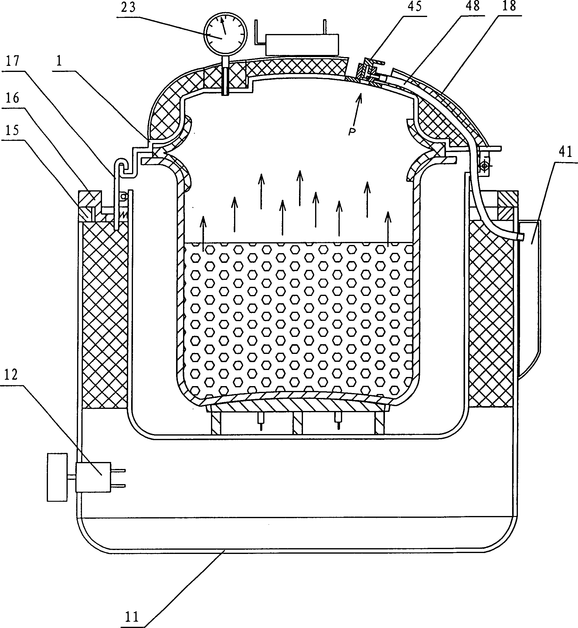
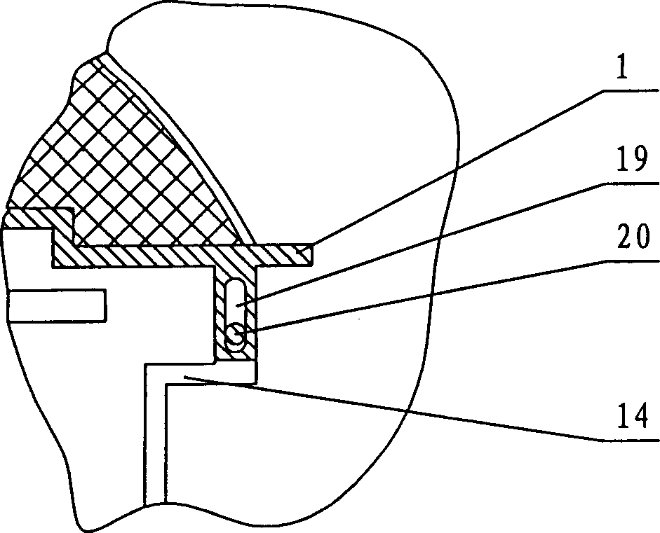
[0039] In the figure, 1 is the pot cover, 2 is the elastic rubber sealing ring, 3 is the gravity pressure limiting valve, 4 is the manual reset pressure switch, 5 is the overpressure safety valve, 6 is the air duct or channel, 7 is the heat insulation layer, 8 is the inner pot, 9 is the automatic reset adjustable air pressure switch, 10 is the electric heating plate, 10.1 is the copper heat conduction layer, 11 is the chassis, 12 is the electric timing starter, 13 is the outer shell, 14 is the middle pot, 15 is the connecting ring, 16 is the locking ring, 16.1 is the oblique slide, 17 is the gusset, 18 is the heat shield, 19 is the oblong slide, 20 is the hinge shaft of the middle pot, 21 is the torsion spring, 23 is the thermometer, 24 is the valve Core, 25 is a safety disc, 26 is a valve cover, 27 is a valve seat, 28 is a sealing ring, 29 is a vapor-liquid guide tube, 30 is a moving contact piece, 31 is a push rod, 32 is a static contact piece, and 33 is a membrane 34 is the pressure adjustment knob, 35 is the pressure diaphragm box, 36 is the switch box, 37 is the manual reset button, 41 is the water box, 42 is the hinge seat of the middle pot, 43 is the hinge shaft of the pot, and 45 is the quick discharge For the air valve, 46 is the exhaust valve seat, 47 is the exhaust valve core, 48 is the vapor-liquid guide pipe, 50 is the exhaust pipe, 51 is the pressure limiting valve spool, 52 is the pressure limiting valve seat, and 53 is exhaust vent.
[0040] See Figure 1-Figure 15 , The pressure-controlled electric pressure cooker includes an inner pot 8 arranged in the outer shell 13 of the pot body, the inner pot 8 is connected with the electric heating plate 10, an elastic sealing ring 2 is arranged between the inner pot 8 and the lid 1, and the outer shell 13 A middle pot 14 is arranged between the inner pot 8 and the middle pot 14 and an insulation layer 7 is arranged between the middle pot 14 and the outer shell 13, and an air pressure switch is arranged on the electric pressure cooker. The air pressure switch includes an enclosure surrounded by the lid 1 and the inner pot 8. The air duct 6 or air duct connected to the chamber, one end of the air duct 6 or the air duct communicates with a pressure diaphragm box 35, the pressure diaphragm box 35 is provided with a movable diaphragm 33 connected to the push rod 31, A moving contact piece 30 is arranged on the other end of the push rod, and the moving contact piece 30 is connected with a static contact piece 32, and the moving contact piece 30 and the static contact piece 32 are respectively electrically connected to the main controller of the electric pressure cooker. There are two air pressure switches, one of which is set on the pot cover 1 and the other on the shell 13; the air pressure switch set on the pot cover 1 is a manual reset air pressure switch 4, and the movable contact piece 30 of the manual reset air pressure switch 4 Connected with a manual reset button 37; the air pressure switch set on the housing 13 is an automatic reset adjustable air pressure switch 9, and the movable contact piece 32 of the automatic reset adjustable air pressure switch 9 is connected with a pressure adjustment knob 34, and the automatic reset The push rod 31 and/or the pressure adjustment knob of the adjustable air pressure switch 9 is provided with a return spring; the return spring part is not shown in the figure, and one end of the air guide tube 6 is opened in the chamber enclosed by the pot cover 1 and the inner pot 8. The other end is in communication with the pressure diaphragm box 35 chamber set on the automatic reset adjustable air pressure switch 9. see Figure 1-Figure 2 , Figure 5-Figure 6.
[0041] The working principle of the automatic reset adjustable air pressure switch: see figure 1 with Figure 5 When the steam pressure in the chamber enclosed by the lid 1 and the inner pot 8 reaches the set pressure value P1, the steam pressure is transmitted to the diaphragm of the automatic reset adjustable air pressure switch 9 through the air duct 6 to push the diaphragm to act, Disconnect the internal moving and static contacts and cut off the current. When the pressure in the chamber enclosed by the lid 1 and the inner pot 8 drops to the set value, the P1 value decreases, the diaphragm is reset, the moving and static contact pieces are connected, the current is turned on again, and the electric heating plate resumes heating. Continuously carry out the work cycle. By turning the pressure adjusting knob, the working pressure of the inner pot can be controlled to change. The user can maintain the working pressure in the pot between P0 and P1 according to the cooking temperature required for different foods.
[0042] Working principle of manual reset air pressure switch: see figure 1 with Figure 6 If the pressure control function of the two components of the automatic reset adjustable air pressure switch 9 and the gravity pressure limiting valve fails, the pressure in the chamber enclosed by the lid 1 and the inner pot 8 will continue to rise, when the set pressure value P3 is reached When P3>P2, when the diaphragm in the manual air pressure reset switch 4 is under pressure, it will push the moving and static contacts to disconnect, cut off the current, and stop heating, so that the pressure of the inner pot will not continue to rise, which is a protection Features. When the pressure drops, the switch cannot automatically turn on the current, which plays a role of safety insurance. The switch can be reset and turned on only when it is required for maintenance and only by manual action. The product will not malfunction and ensure the safety of use.
[0043] The pot cover 1 is provided with a thermometer 23 that displays the temperature in the cavity enclosed by the pot cover 1 and the inner pot 8, see figure 2.
[0044] The function and control principle of the thermometer 23. In the existing pressure cooker, the pressure and temperature are set by the manufacturer in advance, and the temperature in the chamber enclosed by the lid 1 and the inner pot 8 cannot be known during cooking. The user cannot adjust the cooking temperature of the food by himself according to the actual situation. And through this thermometer installed on the lid, the temperature in the pot can be displayed in real time. The user can adjust the cooking temperature at any time by adjusting the automatic reset adjustable air pressure switch according to the displayed temperature, which is greatly convenient to use.
[0045] The middle pot 14 is hinged to one end of the pot cover 1, and is connected with the pot cover at multiple points at the circumferential position, see figure 1 with image 3 , Figure 9-12 , The hinge joint is provided with a middle pot hinge shaft 20, the middle pot hinge shaft 20 is arranged in an oblong chute 19; the bottom edge of the pot cover 1 is provided with an upward hook groove, and the middle pot 14 is arranged on the outer circular side There is a gusset plate 17, the figure shows the structure set on the side of the middle pot, the top of the gusset plate 17 is provided with a downward hook head, the hook head is hooked in the groove at the bottom of the pot cover, the middle part of the gusset plate 17 or The lower part is hinged to the middle pot, and a compression spring is arranged at the lower part of the gusset plate or between the middle part and the middle pot; the figure shows the structure of the lower part of the gusset plate 17 and the middle pot, and a locking ring is arranged between the middle pot 14 and the lid 1 16. The buckle plate 17 cooperates with the locking ring 16. The locking ring 16 is provided with an inclined slide groove 16.1 and a straight slide groove that push the buckle plate to rotate or deflect.
[0046] The principle of automatic buckling and locking of the lid and the middle pot: see Figure 9-10. Close the lid down, and when the outer edge of the lid touches the top of the gusset, the gusset is automatically pushed out. The side of the lid continues to move downward until the bottom of the hook at the top of the buckle plate is higher than the upper end of the arc side of the lid. At this time, turn the locking ring counterclockwise, and the bottom of the buckle plate is in the locking ring sliding groove and the spring outwards. Pushes the top of the gusset plate to turn inward, and the gusset plate is at Picture 10 Buckle the lid of the pot. When heating, the lid will move upwards after receiving a certain pressure, so that the bottom of the arc groove at the top of the gusset and the upper edge of the side of the pot are in contact with each other, and the lid is fixed on the middle pot and bears Work pressure. This structure ensures that the lid cannot be opened as long as there is a certain pressure in the inner pot. Play a safety role to prevent accidental opening of the cover.
[0047] The principle of opening the lid: see Figure 11-12 After the cooking is over, when the lid of the pot needs to be opened, the quick exhaust valve 45 can be opened to quickly reduce the pressure in the pot to zero pressure. At this time, under the action of its own weight, the pot cover moves downwards, so that the arc edge of the pot cover is released from the arc buckle of the gusset plate, and the locking ring is turned clockwise, and the sliding groove slope of the locking ring will buckle. The bottom of the plate is pressed inward, so that the gusset plate is opened outward and separated from the pot cover, so that the pot cover can be opened upwards.
[0048] The connection between the gusset and the lid can also be designed such that the lid is rolled on the inside with an arc edge, and the gusset is arranged on the inside of the edge of the pot to buckle the lid. The principle is the same as the foregoing, and the appearance is more beautiful.
[0049] The lid 1 is hinged to one end of the middle pot 14, see figure 1 with Figure 4 , The hinge is provided with torsion springs 21, the torsion springs 21 arranged in pairs and opposite torsion are respectively sleeved on the hinge shaft 20 of the middle pot; one end of each torsion spring 21 is connected to the lid of the pot, and the other end is connected with The middle pot 14 is crimped; the air guide tube 6 is wound around the middle pot hinge shaft 20 for a few times, then passes around the middle pot hinge shaft 20 and then connects to the automatic reset adjustable air pressure switch 9.
[0050] This torsion spring constitutes a pot lid balancer, and its working principle: in the process of opening and closing the pot lid, the lid will automatically close down due to its own weight, which is inconvenient to use. Two torsion springs are installed at the joint between the lid and the middle pot. The spring is a torsion spring, fixed on the hinge shaft, the lower end bears against the middle pot and the upper end bears against the pot cover, exerting an upward force to the pot cover, which counteracts the gravity of the pot cover. The pot cover is in a state of gravity balance and can be opened and closed at any position without falling downward.
[0051] There is an overpressure safety valve 5 on the lid 1, see figure 1 with Figure 7 The overpressure safety valve 5 communicates with the chamber enclosed by the pot cover 1 and the inner pot 8 through the airflow channel provided on the valve seat 27, the overpressure safety valve 5 also includes a valve core 24 arranged inside, the airflow channel and The lower part of the valve core 24 is connected, and the upper part of the valve core 24 is connected with a fuse 25 pressed between the valve cover 26 and the valve seat 27. The valve cover 26 is provided with a vapor-liquid guide on the side wall of the chamber above the fuse 25 The flow tube 29 or channel, the vapor-liquid guide tube 29 or channel opens in the water receiving box 41 on the side of the housing 13; the vapor-liquid guide tube or channel 29 is covered with a heat insulation layer 18.1.
[0052] The working principle of the overpressure safety valve: see figure 1 with Figure 7. After the pressure control functions of the automatic reset adjustable air pressure switch, the gravity pressure limiting valve, and the manual reset air pressure switch all fail, the pressure in the chamber enclosed by the lid 1 and the inner pot 8 will continue to rise, when the limit pressure P4 is reached , Where P4>P3, the upper end of the valve core 24 under the action of the pressure P4 breaks the metal fuse 25 upwards, and the gas is discharged into the water receiving box through the guide tube 29 on the valve cover, so as to make the pot inside The pressure drops to zero pressure, which plays a role of safety insurance. Through the function of the safety valve, it can be ensured that the working pressure in the pot will not exceed the structural strength of the pot, and the occurrence of safety accidents can be avoided.
[0053] There is a quick exhaust valve 45 on the lid 1, see figure 1 with Figure 8 , The quick exhaust valve 45 includes an exhaust valve core 47 with a handle arranged in the exhaust valve seat 46, and the quick exhaust valve 45 is surrounded by the lid 1 and the inner pot 8 through the gas-liquid passage 46.1 provided thereon The chambers communicate with each other, and the exhaust valve seat 46 is provided with a vapor-liquid outlet, which communicates with the water receiving box 41 provided on the side of the housing 13 through a guide tube 48; the exhaust valve core 47 is provided with a T A gas-liquid passage 47.1 with a font or L-shaped or cross-shaped structure. One end of the gas-liquid passage 47.1 is connected with the gas-liquid passage 46.1 on the exhaust valve seat 46, and the other end is connected with the gas-liquid passage 46.1 on the exhaust valve seat 46. The outlets are connected; a heat shield is arranged outside the guide tube 48 or the passage.
[0054] The working principle of the quick exhaust valve: see Figure 1-Figure 8 , The quick exhaust valve is fixed on the lid, the hole at the bottom of the valve body communicates with the opening of the lid, and the valve core can be rotated 90 degrees in the valve body. When the cooking is over and the lid needs to be opened quickly, turn the valve core to Figure 8 In the state, the gas in the pot is quickly discharged into the water receiving box through the valve body, the valve core, and the guide tube, so that the pressure quickly drops to zero pressure, and the lid is opened. The moisture in the exhaust gas is stored in the water receiving box and can be dumped in time. When cooking, turn the valve core 90 degrees to close the exhaust channel and maintain the corresponding pressure in the pot. The bottom of the valve body is equipped with a sealing ring to press tightly with the lid to prevent air leakage.
[0055] The surface of the electric heating plate 10 is provided with a copper high-efficiency heat conduction layer 10.1, see Figure 13.
[0056] The working principle of this high-efficiency heat-conducting layer and electric heating plate is that a layer of high-efficiency copper heat-conducting layer made of copper material with high thermal conductivity is compounded on the upper surface of the electric heating plate. When energized and heated, the main heat of the electric heating plate passes through the copper The role of the thermal conductive layer is quickly transferred to the bottom of the inner pot, reducing the heat loss in the air, and effectively improving the thermal efficiency of the electric heating plate when heating. The high-efficiency copper thermal conductive layer can be fixed on the upper surface of the electric heating plate by mechanical connection or welding. The other parts of the electric heating plate are composed of electric heating tubes and aluminum materials.
[0057] An electric timer 12 is provided on the housing 13, see figure 1 14, the electric timer 12 is connected in series with the manual reset air pressure switch 4 set on the pot cover 1, the automatic reset adjustable air pressure switch 9 on the shell 13, and the electric heating plate 10, and then connected to both ends of the power supply; The manual reset air pressure switch 4 and the automatic reset adjustable air pressure switch 9 are normally closed.
[0058] A gravity pressure limiting valve is set on the lid 1, see figure 1 with Figure 15 The valve seat 52 of the gravity pressure limiting valve communicates with the chamber enclosed by the pot cover 1 and the inner pot 8 through an exhaust pipe 50. The valve core 51 of the gravity pressure limiting valve has a conical structure, and the valve core 51 is compressed Connected to the outlet of the exhaust pipe 50, an exhaust port 53 is opened on the valve seat 52 at the side of the valve core.
[0059] The working principle of the gravity pressure limiting valve: see figure 1 During the pressurization or heating process, when the set pressure P1 is reached, if the automatic reset adjustable air pressure switch 9 fails and cannot be automatically disconnected, the pressure continues to rise. When the pressure rises to the set value P2, where P2>P1, the gravity pressure limiting valve body is lifted upwards after receiving the pressure, creating a gap to discharge the steam, and the pressure in the chamber drops. The valve body drops to restore the seal, and the pressure rises again. Through continuous circulation, the pressure of the inner pot is maintained within a certain range, which plays a role in limiting a certain pressure.