Non-contact mechanical end face sealing structure

An end-face sealing, non-contact technology, used in engine sealing, mechanical equipment, engine components, etc., can solve the problems of limited pumping effect, poor start-stop effect, short service life, etc., to improve the ability to prevent solid particles, seal The effect of good performance and extended service life

Inactive Publication Date: 2006-09-06
ZHEJIANG UNIV OF TECH
View PDF7 Cites 24 Cited by
  • Summary
  • Abstract
  • Description
  • Claims
  • Application Information

AI Technical Summary

Problems solved by technology

[0003] In order to overcome the limited ability of the seal to prevent solid particles, static pressure effect, hydrodynamic pressure effect, and pumping effect in the prior art, the start-stop effect is poor under low pressure conditions, and the service life is short, and it is especially applied to media containing solid particles , gaseous medium, easy to crystallize, easy to vaporize, poisonous, and highly polluting medium, the lack of

Method used


Image

  • Non-contact mechanical end face sealing structure
  • Non-contact mechanical end face sealing structure
  • Non-contact mechanical end face sealing structure

Examples


Embodiment 1

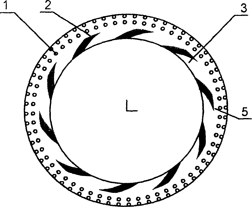
[0023] see figure 1 : A non-contact mechanical end face seal structure, including a moving ring and a static ring of a mechanical seal, and one of the end faces of the moving ring or the static ring is provided with a microgroove 2 symmetrical to the center of rotation, a microporous ring belt, and a microporous ring The belt is arranged upstream of the end face, the microgroove 2 is arranged downstream, and an annular sealing dam is arranged beside the microporous annular belt. Sealing weir 3 is the ungrooved part between microgrooves.

[0024] The annular sealing dam is located downstream of the microporous annulus and is the inner annulus 5 .

[0025] The radial width range of the inner ring is: 0.1-10mm.

[0026] The diameter of the micropores 1 ranges from 10 to 200 μm, the depth-to-diameter ratio ranges from 0.01 to 0.5, and the area density of the micropores ranges from 0.05 to 0.5.

[0027] The groove depth range of the microgroove is: 2-30μm. When the medium is liq...

Embodiment 2

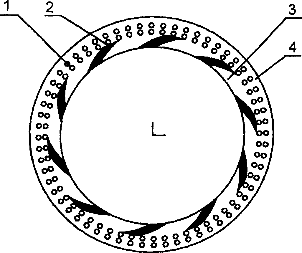
[0033] see figure 2 : A non-contact mechanical end face seal structure, including a moving ring and a static ring of a mechanical seal, and one of the end faces of the moving ring or the static ring is provided with a microgroove 2 symmetrical to the center of rotation, a microporous ring belt, and a microporous ring The belt is arranged upstream of the end face, the microgroove 2 is arranged downstream, and an annular sealing dam is arranged beside the microporous annular belt.

[0034] The annular sealing dam is located upstream of the microporous annular zone and is the outer annular zone 4 .

[0035] The radial width range of the outer ring is: 0.1-10mm.

[0036] The remaining structures and implementation modes of this embodiment are the same as those of Embodiment 1.

Embodiment 3

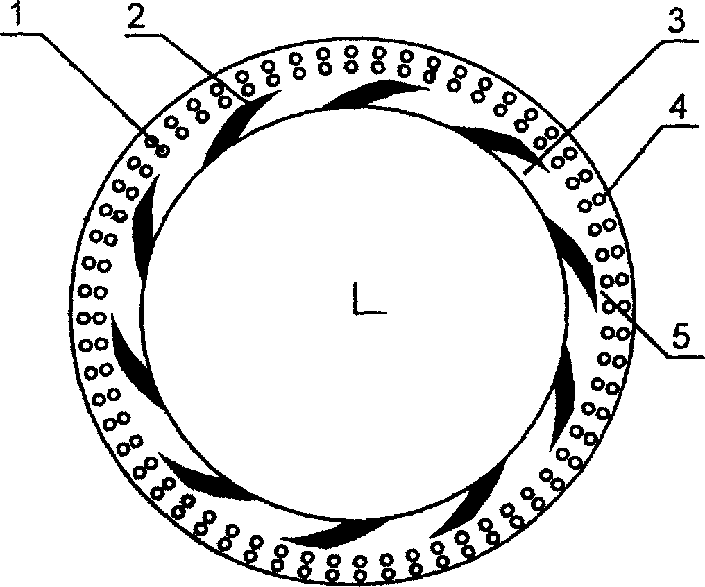
[0038] see image 3 : There are annular sealing dams upstream and downstream of the microporous annulus.

[0039] The radial width range of the annular sealing dam is 0.1-10mm.

[0040] The remaining structures and implementation modes of this embodiment are the same as those of Embodiment 1.


PUM

PropertyMeasurementUnit
Radial widthaaaaaaaaaa
Diameter rangeaaaaaaaaaa
Diameteraaaaaaaaaa

Abstract

The invention relates to a non-contact mechanical end surface sealing structure, which comprises mechanical sealed movable ring and stable ring. While the end surface of stable or movable ring has micro groove and porous zone that symmetry according to the rotational center. Wherein, said zone is at the ascending part of end surface and the micro groove is at the descending part, which has a circular sealing dam beside it. The invention can be used in variable mediums to increase the ability of solid particle, the static pressure property, fluid dynamic pressure property and the pump adsorption property, to attain better sealing effect, with long service life.

Description

(1) Technical field [0001] The invention relates to a non-contact mechanical end face seal, which is suitable for the shaft end sealing device of rotating shafts of various compressors, pumps, kettle stirrers and the like. (2) Background technology [0002] The rotating shaft of rotary fluid machinery generally uses ordinary mechanical seals or contact mechanical end face seals. In the 1990s, world seal giants such as John Crane Company successively introduced spiral groove end face mechanical seals, such as dry gas end face seals. Seal (referred to as DGS, see Lubrication Engineering, 1990, 46 (9): pp607) and upstream pumping mechanical seal (referred to as UP-Stream MS, see Lubrication Engineering, 1990, 46 (4): pp213, USA Patent 4,290,611 and Chinese patent 03134193.4). Around these two types of seals, multiple inventions have subsequently appeared, wherein in addition to unidirectional DGS and UP-Stream MS, there are also bidirectional DGS and UP-Stream MS (see Lubricat...

Claims


Application Information

Patent Timeline
IPC IPC(8): F16J15/16
Inventor 彭旭东李纪云
Owner ZHEJIANG UNIV OF TECH
Why Eureka
Try Eureka