
Solution desorption refrigeration circulation device

A refrigeration cycle and desorption technology, used in refrigerators, refrigeration and liquefaction, adsorption machines, etc., can solve problems such as the limitation of refrigeration coefficient, and achieve the effect of improving refrigeration coefficient

Inactive Publication Date: 2006-09-06
OCEAN UNIV OF CHINA
View PDF0 Cites 0 Cited by
  • Summary
  • Abstract
  • Description
  • Claims
  • Application Information

AI Technical Summary

Problems solved by technology

The cooling capacity of this device is limited by the latent heat value of the phase change of the working medium, so the refrigeration coefficient is also limited by this

Method used


Image

  • Solution desorption refrigeration circulation device

Examples


Embodiment Construction

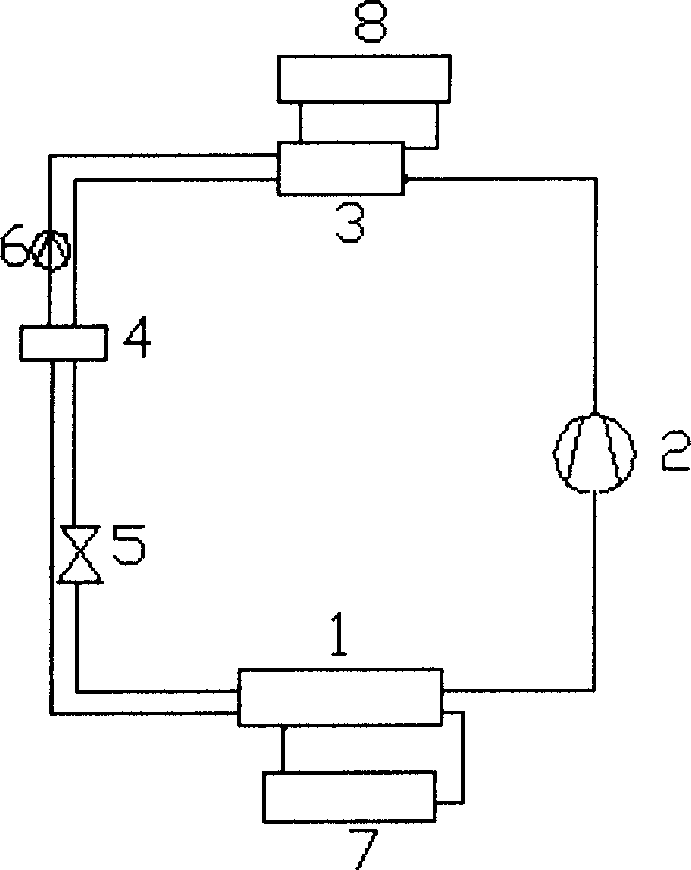
[0007] A solution desorption refrigeration cycle device is characterized in that there is a low-pressure generator 1, which has an outlet connected to the inlet of the compressor 2 through a pipeline, an inlet connected to the heat exchanger 4 through a pipeline and a throttle valve 5, and its other The outlet is directly connected to the inlet of the heat exchanger 4 through a pipeline, and two interfaces are respectively connected to the inlet and outlet of the low-temperature heat storage 7 through a pipeline; one inlet of the absorber 3 is connected to the outlet of the compressor 2 through a pipeline, and the other outlet is connected through a pipeline It is connected with the inlet of the heat exchanger 4, and the other inlet is connected with the outlet of the solution pump 6 through a pipeline, and the outlet of the heat exchanger 4 is connected with the solution pump 6 through a pipeline; the absorber 3 also has two interfaces with the high temperature heat store 8 thr...


PUM


Abstract

The invention relates to a solution desorption refrigeration cycle device, which is characterized in that: it has a low-pressure generator, which has a outlet via channel connected to the inlet, and a inlet via channel connected to the throat valve and the heat exchanger, while another outlet via channel is connected to the inlet of heat exchanger and another two interfaces via channels connected to the inlet and outlet of low-temperature heat base; one inlet of adsorbed via channel is connected to the outlet of compressor, while another outlet is connected to the solution pump; another two interfaces of adsorbed via channel is connected to the inlet and outlet of high-temperature heat base. The invention uses solution to generate desorption in low-temperature to generate the refrigerator, which can attain higher unit refrigerator than steam compress refrigeration cycle device, with improved refrigeration factor.

Description

technical field [0001] The invention relates to a solution desorption refrigerating cycle device, which utilizes working fluids such as ammonia water to perform solution desorption and absorb heat at low temperature and low pressure to generate cooling capacity. Background technique [0002] As far as the inventor knows, in the existing refrigerating devices, as the vapor compression refrigeration cycle device is mainly composed of a compressor, an evaporator, a condenser, and a throttling device, it uses hydrocarbons or ammonia as a circulating working medium (refrigeration) agent), relying on the evaporation (physical phase change) of the working fluid in the evaporator to absorb heat to produce a refrigeration effect. The outlet of the evaporator is connected to the inlet of the compressor. The steam generated in the evaporator is compressed by the compressor to condense. The outlet of the compressor is connected to the inlet of the condenser. The steam is sent to the con...

Claims


Application Information

Patent Timeline
Patent Type & Authority Applications(China)
IPC IPC(8): F25B15/04
CPCY02B30/62Y02A30/27
Inventor 梅宁李艳
Owner OCEAN UNIV OF CHINA
Learn More