CO2 refrigeration piston compressor with turbine expansion mechanism

A technology of turbo expansion and compressor, which is applied in the direction of machines/engines, piston pumps, mechanical equipment, etc., can solve the problems of low energy efficiency and difficulty in popularization, so as to improve operating energy efficiency, increase unit cooling capacity, and reduce motors The effect of power

Active Publication Date: 2021-10-26
南京久鼎环境科技股份有限公司
View PDF16 Cites 0 Cited by
  • Summary
  • Abstract
  • Description
  • Claims
  • Application Information

AI Technical Summary

Problems solved by technology

of which CO 2 Refrigerant is one of the hottest in recent years, and it is used in various refrigeration fields, but CO 2 In the refrigeration and freezing industry, because the energy efficiency is not as good as that of R22, R507, R134a and other freon refrigerants, it is relatively difficult to promote. In order to improve CO 2 energy efficiency of refrigeration systems, this device was developed

Method used


Image

  • CO2 refrigeration piston compressor with turbine expansion mechanism
  • CO2 refrigeration piston compressor with turbine expansion mechanism
  • CO2 refrigeration piston compressor with turbine expansion mechanism

Examples


Embodiment 1

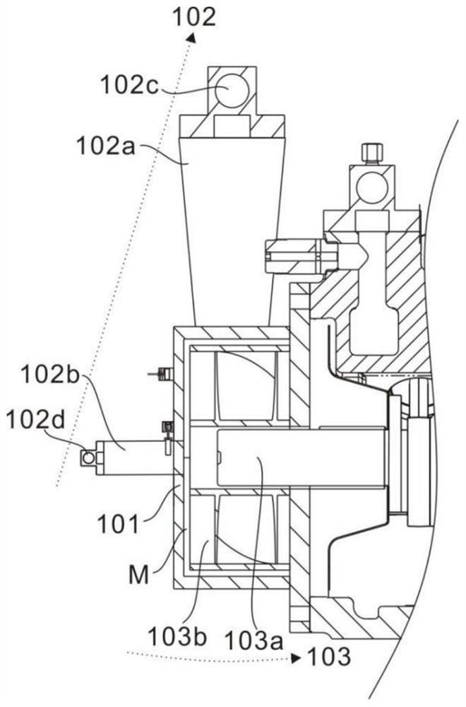
[0033] refer to figure 1 and figure 2 , is the first embodiment of the present invention, which provides a CO with a turbo expansion mechanism 2 Refrigeration piston compressor, CO with turbo expansion mechanism 2 The refrigeration piston compressor includes an expansion unit 100 , and the expansion unit 100 includes an expansion shell 101 , a gas channel 102 and a working assembly 103 .

[0034] Specifically, an accommodating space M is provided inside the expansion shell 101, and the normal temperature and high pressure CO 2 After the gas enters the expansion shell 101, because the gas enters a relatively low-pressure (such as normal temperature) space from a high-pressure state, it can expand in the accommodation space M, thereby acting externally, wherein the normal temperature and high pressure CO 2 The pressure range of the gas is 7MPa-13MPa, and the temperature range is 15°C-40°C.

[0035] The gas passage 102 of the expansion unit 100 includes an intake passage 102...

Embodiment 2

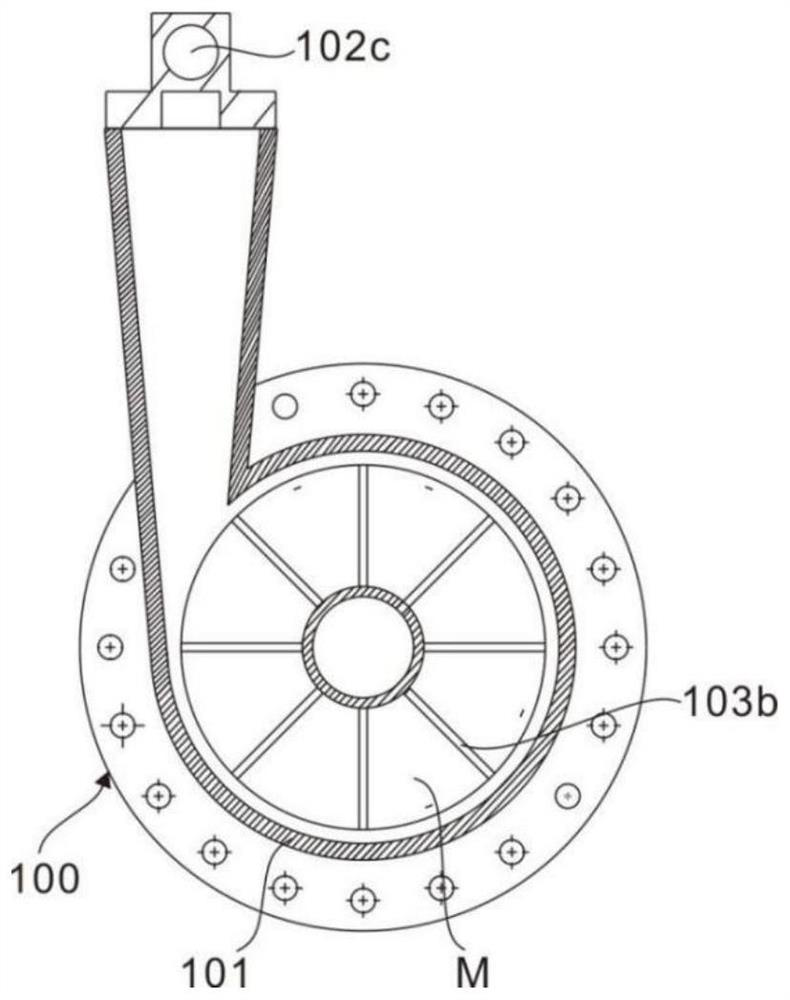
[0039] refer to image 3 and Figure 4 , is the second embodiment of the present invention, in this embodiment,

[0040] The gas channel 102 of the expansion unit 100 also includes a first suction valve 102c and a first exhaust valve 102d. The first suction valve 102c is arranged at one end of the gas intake channel 102a for controlling the external CO 2 For the input of gas, the first exhaust valve 102d is set at one end of the exhaust channel 102b to control the discharge of CO 2 The expanded CO in the accommodation space M 2 gas.

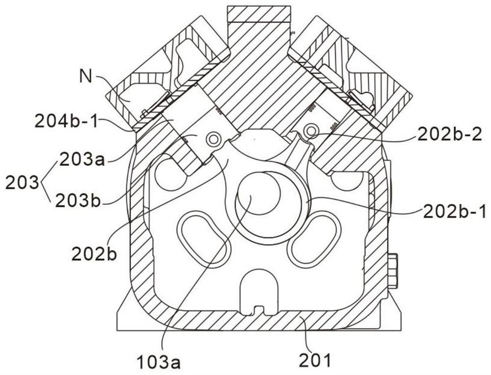
[0041] The expansion unit 100 is connected with the compression unit 200 , and the compression unit 200 includes a compression housing 201 and a power assembly 202 . Wherein, one side of the compression housing 201 is provided with a partition 201a, and the partition 201a is arranged on the side adjacent to the expansion housing 101, the compression housing 201 is used to seal the compression unit 200, and the partition 201a connects the expa...

Embodiment 3

[0045] refer to Figure 1~4 , is the third embodiment of the present invention, in this embodiment,

[0046] Specifically, the compression unit 200 also includes a compression assembly 203, which includes a cylinder 203a and a piston 203b. The cylinder 203a is disposed inside the compression housing 201, and the piston 203b is movably connected to the second ring 202b-2 at one end of the connecting rod 202b. Into the cylinder 203a, the diameter of the first ring 202b-1 is larger than the diameter of the second ring 202b-2, when the transmission part 103a rotates, it drives the connecting rod 202b to move, and the rotary motion of the transmission part 103a is converted into the reciprocating motion of the piston 203b through the connecting rod 202b movement, so that the low-temperature and low-pressure CO in the cylinder 203a 2 The gas is compressed into high temperature and high pressure CO 2 gas.

[0047] Wherein, compression housing 201 also comprises motor cover 201b an...


PUM


Abstract

The invention discloses a CO2 refrigeration piston compressor with a turbine expansion mechanism. The CO2 refrigeration piston compressor comprises an expansion unit and a compression unit, wherein the expansion unit comprises an expansion shell, a gas channel and an acting assembly, the acting assembly comprises a transmission part and a rotating part, and the rotating part is arranged in the expansion shell and connected with the transmission part; and the compression unit comprises a motor, a connecting rod, a piston and an air cylinder. According to the CO2 refrigeration piston compressor, the acting assembly is coaxially connected with the motor, and normal-temperature high-pressure CO2 gas expands in the expansion shell to act outwards, so that power consumption of the motor is saved; and meanwhile, the dryness of the high-pressure CO2 in the fluid state after isentropic expansion is smaller than that of the high-pressure CO2 in the fluid state after adiabatic throttling, and therefore the unit refrigerating capacity is improved; According to a system applying the CO2 refrigeration piston compressor, the motor power in the working process of the compressor is reduced, the refrigerating capacity of the system is increased, and therefore the operation energy efficiency of the system is improved.

Description

technical field [0001] The present invention relates to CO 2 In the field of refrigeration technology, especially a CO with turbo expansion mechanism 2 Refrigeration piston compressor. Background technique [0002] At present, in the field of refrigeration and air conditioning, as people pay more and more attention to environmental protection, natural environmentally friendly refrigerants have received more attention again. of which CO 2 Refrigerant is one of the hottest in recent years, and it is used in various refrigeration fields, but CO 2 In the refrigeration and freezing industry, because the energy efficiency is not as good as that of R22, R507, R134a and other freon refrigerants, it is relatively difficult to promote. In order to improve CO 2 The energy efficiency of refrigeration systems was developed for this device. Contents of the invention [0003] The purpose of this section is to outline some aspects of embodiments of the invention and briefly describe ...

Claims


Application Information

Patent Timeline
Patent Type & Authority Applications(China)
IPC IPC(8): F01K25/10F01K13/00F01K13/02F01D15/10F04B39/06F04B35/04
CPCF01K25/103F01K13/00F01K13/02F01D15/10F04B39/06F04B35/04Y02B30/70
Inventor 赵东华张显鹏杨长军
Owner 南京久鼎环境科技股份有限公司
Why Eureka
Try Eureka