Taking lens system
A lens system and lens technology, applied in the fields of lenses, instruments, optics, etc., can solve the relationship between the inappropriate shape of the first lens element, difficulty in manufacturing peripheral performance, and the focal power of the first and second lens elements Inappropriate and other problems, to achieve the effect of low cost, small cost, and reduced sensitivity
- Summary
- Abstract
- Description
- Claims
- Application Information
AI Technical Summary
Problems solved by technology
Method used
Image

Examples
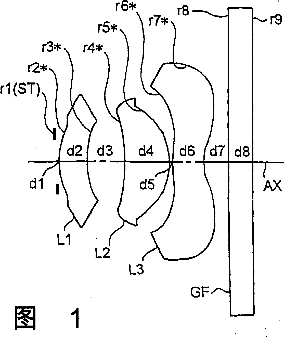
example 1
[0100] [Asphere data of surface r2]
[0101] ε=-0.77750×10, A4=0.30133, A6=-0.18716
[0102] [Asphere data of surface r3]
[0103] ε=-0.32536×10, A4=0.12859, A6=0.96276×10 -1
[0104] [Asphere data for surface r4]
[0105] ε=-0.17634×10 2 , A4=0.16810, A6=0.37183×10 -1 , A8=0.13745, A10=-0.27842×10 -1
[0106] [Asphere data of surface r5]
[0107] ε=0.29577, A4=0.49555×10 -1 , A6=-0.17811×10 -1 , A8=-0.14756×10 -1 , A10=0.29727×10 -1
[0108] [Asphere data of surface r6]
[0109] ε=0.17544×10, A4=-0.24387, A6=0.11001, A8=-0.45300×10 -1 , A10=0.24779×10 -1 , A12=-0.87870×10 -2
[0110] [Asphere data for surface r7]
[0111] ε=-0.40000×10, A4=-0.15919, A6=0.91191×10 -1 , A8=-0.38452×10 -1 , A10=0.91696×10 -2 , A12=-0.97609×10 -3
[0112] Table 2
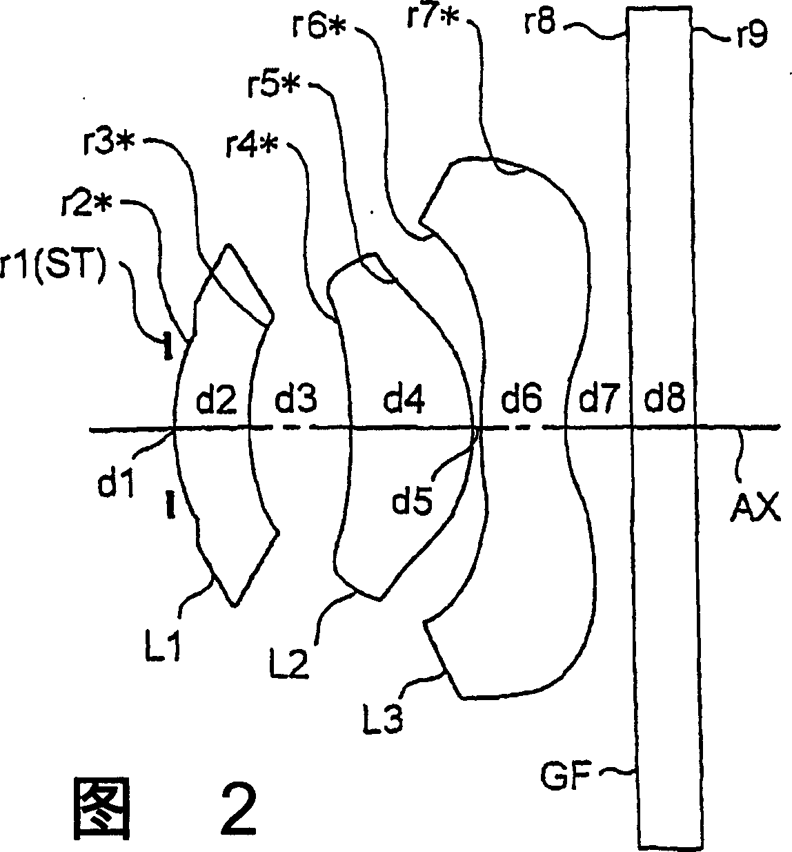
example 2
[0115] [Asphere data of surface r2]
[0116] ε=-0.52989×10, A4=0.28235, A6=-0.14635
[0117] [Asphere data of surface r3]
[0118] ε=-0.35960×10, A4=0.13545, A6=0.68161×10 -1
[0119] [Asphere data for surface r4]
[0120] ε=-0.68322×10, A4=-0.38560×10 -1 , A6=-0.22741×10 -1 , A8=0.94379×10 -2 , A10=0.36530×10 -1
[0121] [Asphere data of surface r5]
[0122] ε=0.45134, A4=-0.16882×10 -1 , A6=-0.44234×10 -2 , A8=0.17818×10 -1 , A10=0.55365×10 -2
[0123] [Asphere data of surface r6]
[0124] ε=0.20629×10, A4=-0.33010, A6=0.13147, A8=-0.49477×10 -1 , A10=0.31953×10 -1 , A12=-0.10098×10 -1
[0125] [Asphere data for surface r7]
[0126] ε=-0.40000×10, A4=-0.15498, A6=0.82349×10 -1 , A8=-0.35200×10 -1 , A10=0.88419×10 -2 , A12=-0.95148×10 -3
[0127]
PUM
 Abstract
Description
Claims
Application Information
 - R&D Engineer
- R&D Manager
- IP Professional
- Industry Leading Data Capabilities
- Powerful AI technology
- Patent DNA Extraction
Browse by: Latest US Patents, China's latest patents, Technical Efficacy Thesaurus, Application Domain, Technology Topic.
© 2024 PatSnap. All rights reserved.Legal|Privacy policy|Modern Slavery Act Transparency Statement|Sitemap