Tensioner

A technology of tensioner and shaft components, applied in belts/chains/gears, mechanical equipment, transmission devices, etc., can solve the problems of increased engine output loss, increased friction, inappropriateness, etc., to reduce output loss and stabilize amplitude. The effect of suppression, fine and stable amplitude suppression

Inactive Publication Date: 2006-09-06
NHK SPRING CO LTD
View PDF1 Cites 2 Cited by
  • Summary
  • Abstract
  • Description
  • Claims
  • Application Information

AI Technical Summary

Problems solved by technology

[0017] However, in these corresponding structures, conversely, the propulsion (advance) characteristic of the propulsion shaft 130 tends to be enhanced
In addition, when the propulsion shaft 130 is pushed beyond the req

Method used


Image

  • Tensioner
  • Tensioner
  • Tensioner

Examples


Embodiment 1

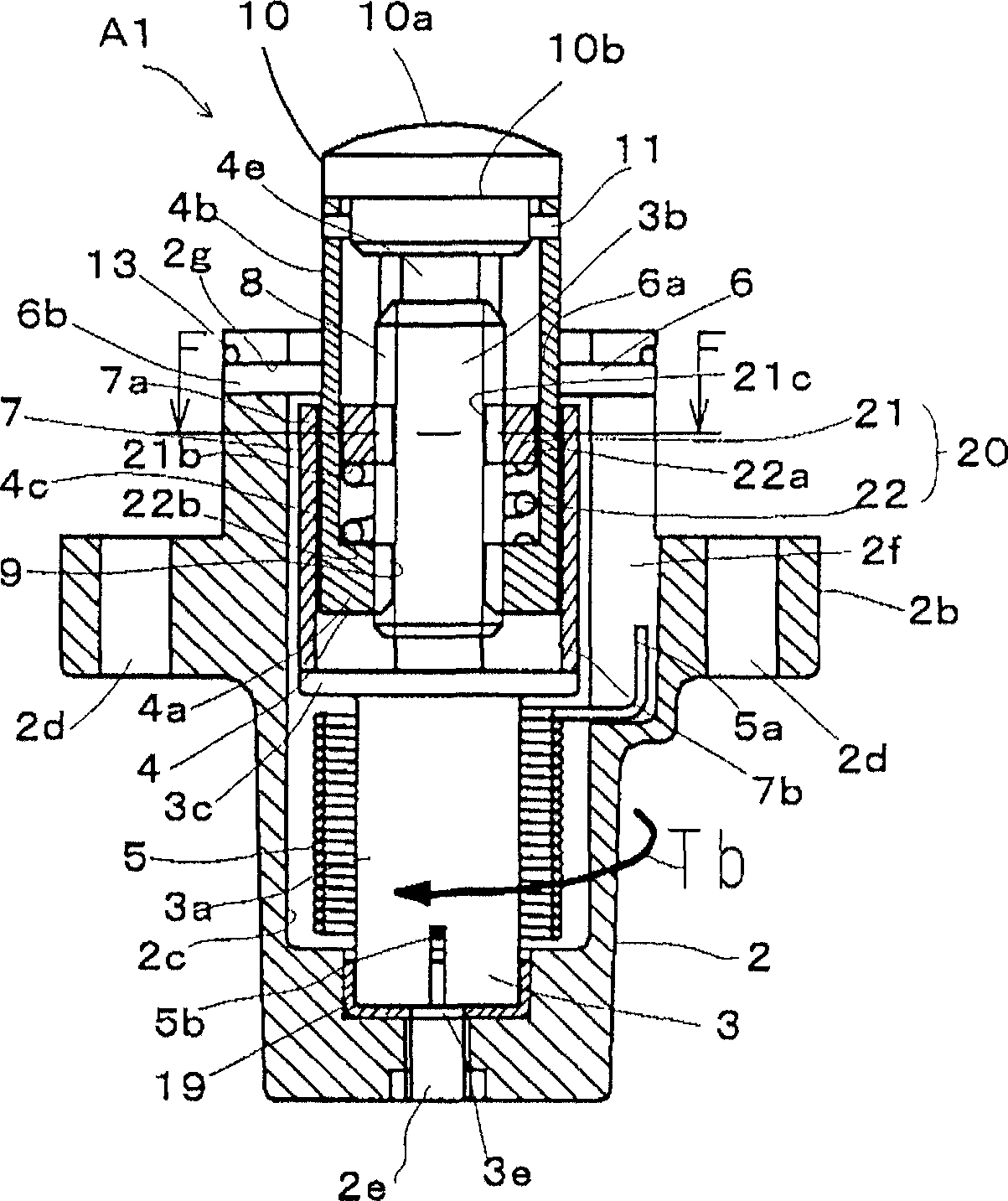
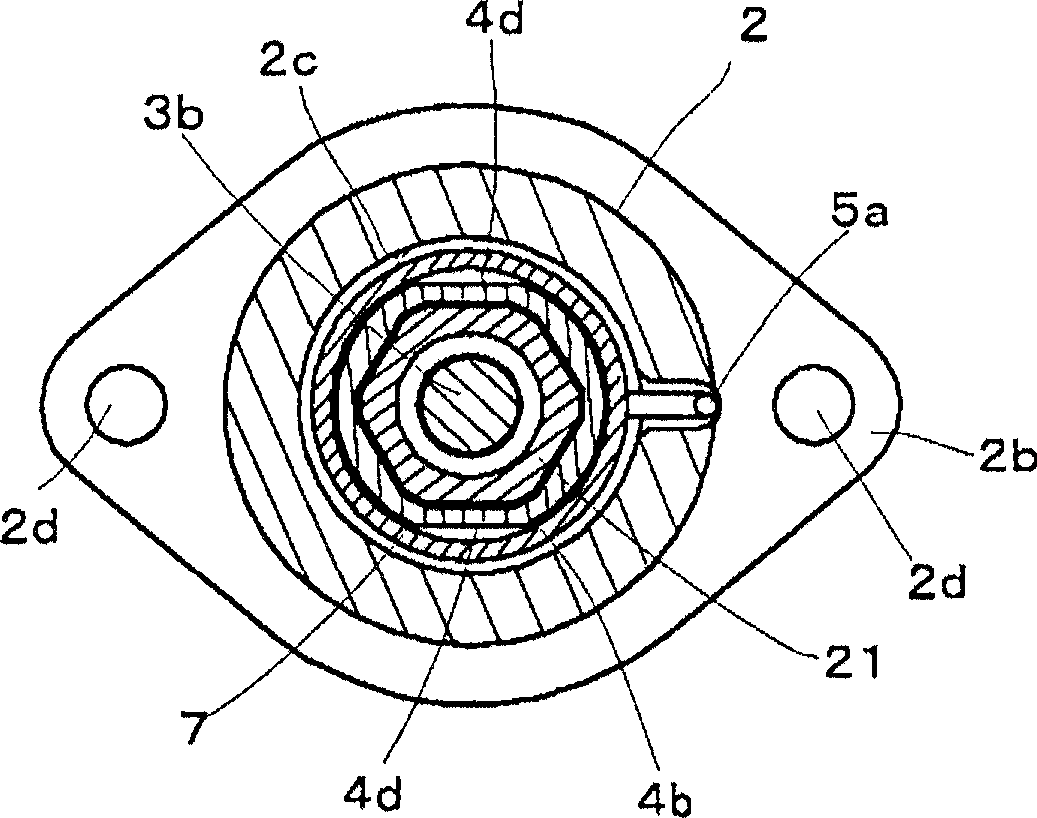
[0094] figure 1 is a longitudinal sectional view showing a tensioner A1 according to Embodiment 1 of the present invention, figure 2 yes figure 1 The F-F line section view. The tensioner A1 includes a housing 2 , a first shaft member 3 , a second shaft member 4 , a torsion spring 5 , a bearing 6 , a partition 7 and a resistance moment adding mechanism 20 .

[0095] The casing 2 is formed substantially in a bottomed cylindrical shape having a flange portion 2b in the middle of a cylindrical portion 2a. Furthermore, a storage hole 2c extending to the front end in the axial direction (propelling direction) is formed inside the cylindrical body portion 2a. The front end portion of the housing hole 2c is open, and a combination of the first shaft member 3, the second shaft member 4, the torsion spring 5, the spacer 7, and the resistance moment adding mechanism 20 is accommodated in the housing hole 2c.

[0096] The flange portion 2b of the housing 2 is used for mounting to a...

Embodiment 2

[0133] Figure 6 It is a longitudinal sectional view of the tensioner A2 of the second embodiment of the present invention.

[0134] In the second embodiment (A2), the cylindrical part 4b is cut off from the base end part 4a of the second shaft member 4 in the first embodiment (A1) to form a separate cylindrical part 41. Other configurations are similar to those of the embodiment One (A1) is the same. That is, the second shaft member 4 in the second embodiment (A2) is composed of the main member 40 and the cylindrical member 41 corresponding to the base end portion 4a of the second shaft member 4 in the first embodiment (A1) (corresponding to the claim 8 invention).

[0135] Figure 7 is a longitudinal sectional view showing the cylindrical member 41, Figure 8 is its top view.

[0136] Such as Figure 8 As shown, the cylindrical member 41 is formed into a non-circular cross-sectional shape having parallel cut portions 41c, 41d on both the inner surface and the outer sur...

Embodiment 3

[0157] Figure 15 It is a longitudinal sectional view showing the tensioner A3 of Embodiment 3 of the present invention, Figure 16 yes Figure 15 H-H line sectional view.

[0158] Such as Figure 15 As shown, compared with the above-mentioned embodiment, the tensioner A3 of this embodiment differs only in the configuration of the resistive moment adding mechanism 20, which adopts the arrangement of the second shaft member 4 and the third shaft member 21 turned upside down. The structure of other structures is basically the same as the above-mentioned embodiment. That is, the resistive torque adding mechanism 20 is configured such that the third shaft member 21 screwed to the threaded portion 3 b of the first shaft member 3 is disposed below the base end portion of the second shaft member 4 , and is connected by the connection member through the coil spring 22 . 50 is connected to the second shaft member 4 .

[0159] Figure 17 It is a longitudinal sectional view showing...


PUM


Abstract

The present invention provides a tensioner capable of stably suppressing the amplitude of both extension and return operations in a wide range of engine speeds even against a strong input vibration load from the engine. The first shaft member (3) and the second shaft member (4) screwed together by the threaded parts (8, 9) are accommodated in the housing (2), and the first shaft member (3) is forced to A torsion spring (5) that rotates in one direction. The rotation of the second shaft part (4) is restricted, and the rotational force of the torsion spring (5) is converted into the propulsion force of the second shaft part (4). Between the first shaft member (3) and the second shaft member (4), there is a resistance that always generates a resistance moment against the external input load input to the second shaft member (4) during both the extension operation and the return operation. The torque adding mechanism (20) can suppress the vibration amplitude of the second shaft member (4) extremely finely and stably.

Description

technical field [0001] The invention relates to a tensioner for adjusting the tension of an endless belt or chain to keep it constant. Background technique [0002] The function of the tensioner is to press the timing chain or the timing belt used on the car engine with a specified force, and keep the tension constant when these are stretched or slack. [0003] Figure 25 It is a layout diagram showing the state when the tensioner 100 is mounted on the engine body 200 of the automobile. A pair of cam sprockets 210 , 210 and a crank sprocket 220 are arranged inside the engine body 200 , and an endless timing chain 230 is stretched between these sprockets 210 , 210 , 220 . In addition, a chain guide 240 is swingably disposed on the moving path of the timing chain 230 , and the timing chain 230 can slide on the chain guide 240 . A mounting surface 250 is formed on the engine body 200 , and the tensioner 100 is fixed to the mounting surface 250 by bolts 270 passing through mou...

Claims


Application Information

Patent Timeline
IPC IPC(8): F16H7/08
CPCF16H7/08F16H2007/0857F16H2007/081
Inventor 小林贵雄天野种平
Owner NHK SPRING CO LTD
Why Eureka
Try Eureka