Method for the magnetic-inductive determination of the flow rate of a medium

A magnetic induction and medium technology, applied to volume/mass flow generated by electromagnetic effects, using electromagnetic flowmeters to detect fluid flow, measuring flow/mass flow, etc., can solve problems such as not being widely used, measurement errors, and misinterpretations

Inactive Publication Date: 2006-09-06
ENDRESS HAUSER FLOWTEC AG
View PDF2 Cites 1 Cited by
  • Summary
  • Abstract
  • Description
  • Claims
  • Application Information

AI Technical Summary

Problems solved by technology

Although automatic cleaning of measuring electrodes has significant advantages over manually performed cleaning, the known automatic cleaning of measuring electrodes also has disadvantages: firstly, it is not widely applicable to deposits of all materials and is only suitable for eliminating conductive deposits
However, measurement errors and misinterpretations occur when the relaxation time of the answer signal of the test signal at the measuring electrodes exceeds the duration of the measuring cycle

Method used


Image

  • Method for the magnetic-inductive determination of the flow rate of a medium
  • Method for the magnetic-inductive determination of the flow rate of a medium

Examples


Embodiment Construction

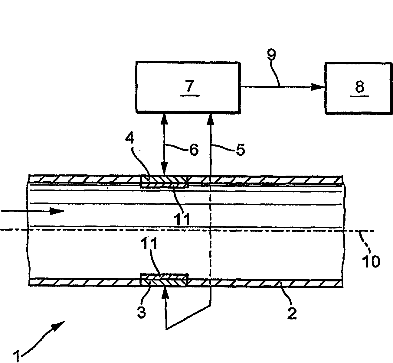
[0023] figure 1 A schematic diagram of a device 1 according to the invention is shown. In the measuring tube 2 of the flow measuring device not shown in particular in the present invention, a medium, likewise not shown in particular, flows in the direction of the measuring tube axis 10 . The medium is at least to a small extent electrically conductive. The measuring tube 2 itself is made of a non-conductive material, or at least is coated on its inner side with a non-conductive material. As a result of a magnetic field perpendicular to the flow direction of the medium, typically generated by two diametrically opposed electromagnets (not shown), charge carriers in the medium migrate to the oppositely polarized measuring electrodes 3; 4 . The voltage generated between the two measuring electrodes 3 , 4 is proportional to the average medium flow velocity over the cross-section of the measuring tube 2 , ie it is a measure of the volume flow of the medium in the measuring tube 2 ...


PUM


Abstract

The invention relates to a magnetic-inductive method for determining the flow rate of a medium that penetrates a measuring tube (2) in the direction of the axis thereof. In order to be able to detect the formation of a coating at an early stage and with great reliability, a test pulse (Up) having a defined duration (tp) is applied to the measuring electrode (3, 4); at least one response signal to the test pulse (Up) is determined at least at two measurement times (t1, t2) located within a time slot (tend tbegin) which is selected such that no foreseeable unwanted signals occur at the measuring electrode (3, 4) during said time slot (tend tbegin); the relaxation period (t) or the time it takes the measuring electrode (3, 4) to reach a predefined discharged state (Ui) is determined based on the response signal determined at the measurement times (t1, t2); a malfunction of the measuring electrode (3, 4) is or can be detected based on the determined relaxation period (t) or the time it takes the measuring electrode (3, 4) to reach the defined discharged state (Ui).

Description

technical field [0001] The invention relates to a method for magnetically inductively determining the flow velocity of a medium flowing through a measuring tube in the direction of the measuring tube axis, wherein the magnetic field cuts the measuring tube substantially perpendicularly to the measuring tube axis, wherein at least one A measuring voltage is induced in the measuring electrode, and the induced measuring voltage provides information about the volume flow of the medium in the measuring tube. Furthermore, the invention relates to a corresponding device. Background technique [0002] Magnetic-inductive flowmeters use the principle of electromagnetic induction for volumetric flow measurement: Charge carriers of a medium moving perpendicular to a magnetic field induce a voltage in measuring electrodes which are likewise arranged essentially perpendicular to the direction of flow of the medium. This voltage induced in the measuring electrodes is proportional to the a...

Claims


Application Information

Patent Timeline
Patent Type & Authority Applications(China)
IPC IPC(8): G01F1/60G01F25/00G01F1/58G01N27/38
CPCG01F1/58G01F1/60G01F15/12G01F25/10
Inventor 托马斯·布德米格尔
Owner ENDRESS HAUSER FLOWTEC AG
Why Eureka
Try Eureka