

Modular sleeve forming method and its device
A molding method and a technology of setting sleeves, which are applied in the field of film processing and can solve the problems of uneven heating of blanks, power consumption, and large heat loss.
- Summary
- Abstract
- Description
- Claims
- Application Information
AI Technical Summary
Problems solved by technology
Method used
Image

Examples
Embodiment Construction
[0015] The invention relates to a molding method of a calibrating sleeve. The method is as follows: put the blank of the calibrating sleeve into a forming mold, put the mold covered with the blank on the conveyor belt and enter it into a water tank filled with constant temperature water, and the blank is heated and formed in the water tank. was taken out of the tank.
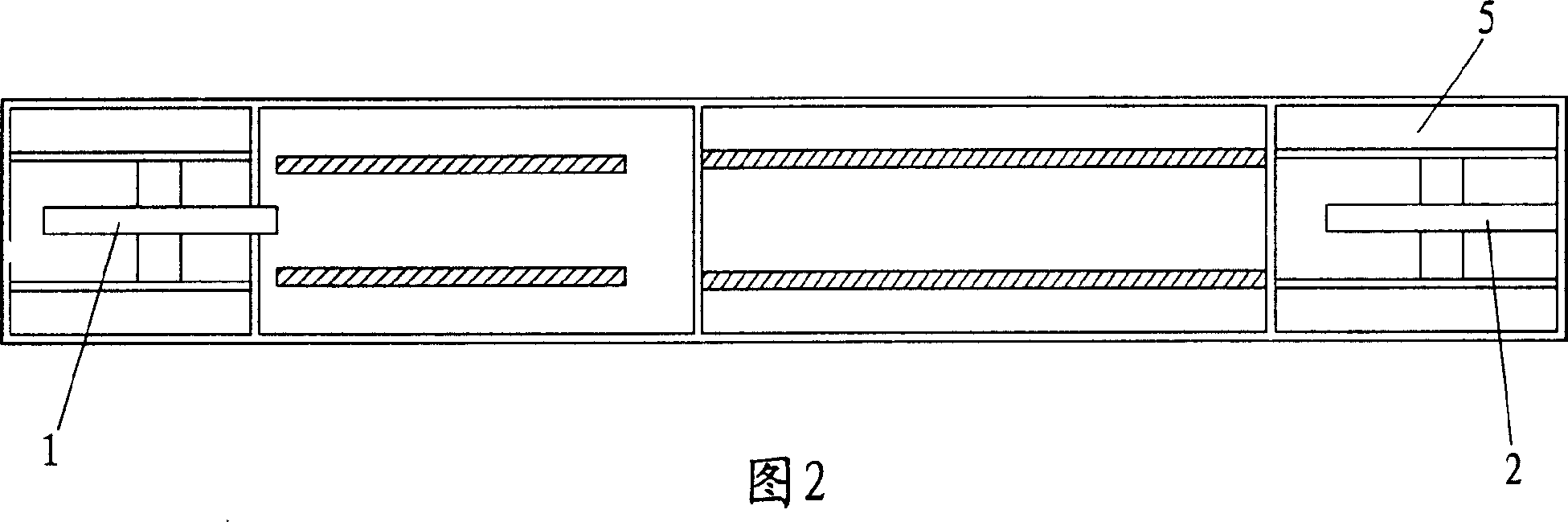
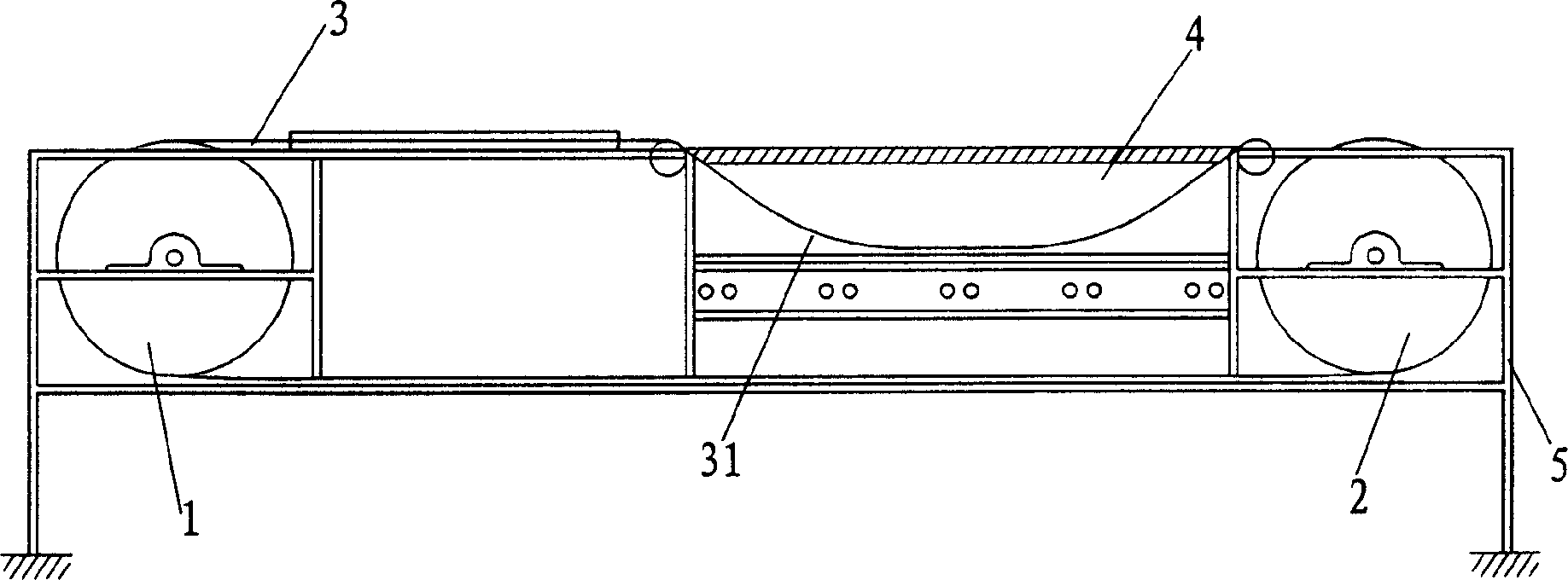
[0016] figure 2, image 3 It is a sizing set molding device designed by the above-mentioned method, and it includes a driving sprocket 1, a driven sprocket 2, a conveyor belt 3, a water tank 4, and a frame 5.
[0017] The driving sprocket 1 and the driven sprocket 2 are installed at both ends of the frame 5; the conveyor belt 3 is sleeved on the driving sprocket 1 and the driven sprocket 2. The driving sprocket 1 is sleeved on the output shaft of the motor, and can rotate with the rotation of the output shaft of the motor, driving the conveyor belt 3 to rotate circularly around the driving sprocket 1 and the dr...
PUM
 Abstract
Description
Claims
Application Information