Active matrix type display device and driving method thereof

A display device and active matrix technology, applied to lighting devices, static indicators, instruments, etc., can solve the problem of extinguishing organic EL elements 216, achieve the effect of improving display quality and suppressing afterimages

Active Publication Date: 2006-09-13
SANYO ELECTRIC CO LTD
View PDF1 Cites 9 Cited by
  • Summary
  • Abstract
  • Description
  • Claims
  • Application Information

AI Technical Summary

Problems solved by technology

On the other hand, according to the display signal D supplied to the gate, when the driving TFT 214 is in a non-conductive state, since the current does not flow through the driving TFT 214, the organic EL element 216 is turned off.

Method used


Image

  • Active matrix type display device and driving method thereof
  • Active matrix type display device and driving method thereof
  • Active matrix type display device and driving method thereof

Examples


Embodiment Construction

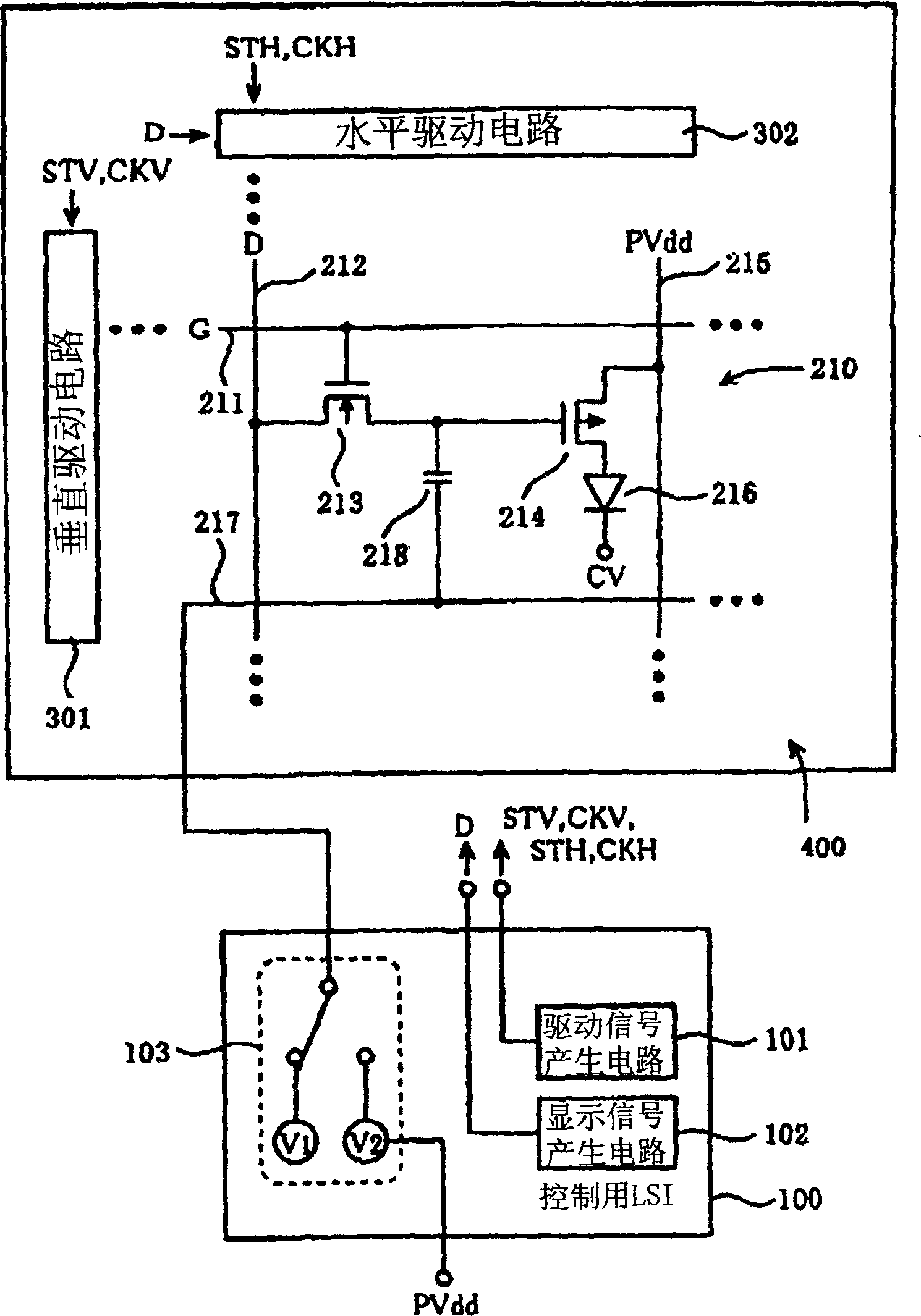
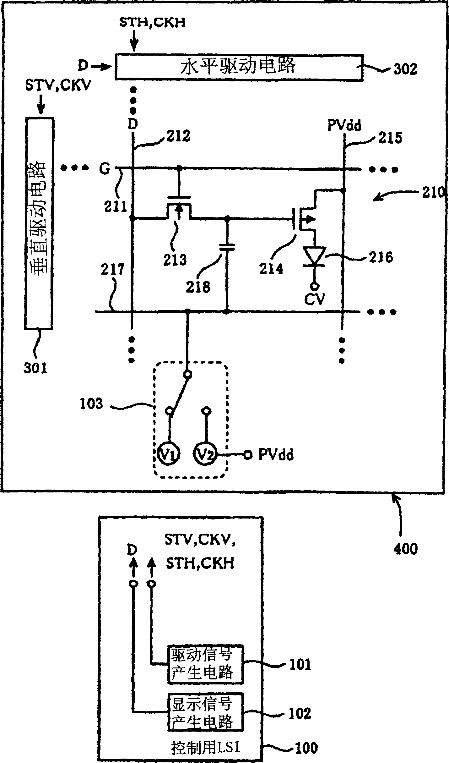
[0039] Next, an organic EL display device and a driving method thereof according to an embodiment of the present invention will be described with reference to the drawings. figure 1 is an equivalent circuit diagram of the organic EL display device. exist figure 1 Among the plurality of display pixels arranged in a matrix on the display panel 400 , only one display pixel 210 is displayed. exist figure 1 in, with image 3 The same constituent parts are given the same reference numerals and their descriptions are omitted.

[0040] In this organic EL display device, a control LSI (Large Scale Integrated Circuit) of the control circuit of the display panel 400 is connected to the vertical drive circuit 301, the horizontal drive circuit 302 of the display panel 400, and the storage capacitance line 217 of the display pixel 210. )100.

[0041] The control LSI 100 includes: a driving signal generating circuit 101 for generating driving signals such as a vertical start pulse sig...


PUM


Abstract

A residual image effect is suppressed to improve quality of display of an active matrix type display device. An electric potential switching circuit switches an electric potential on a capacitor line from a first capacitor electric potential (ground electric potential, for example) to a second capacitor electric potential (power supply electric potential, for example) during a blanking period. At that time, an electric potential at a gate of a driver transistor is raised by capacitive coupling through a storage capacitor. As a result, the electric potential at the gate of the driver transistor becomes higher than an electric potential at a source of the driver transistor. Assuming that holes are trapped in a gate insulation film of the driver transistor due to writing-in of a display signal during a preceding frame period, the holes are extracted from the gate insulation film to the source or a drain of the driver transistor. With this, electric characteristics of the driver TFT are initialized. And the electric potential switching circuit switches the electric potential on the capacitor line back to the first capacitor electric potential from the second capacitor electric potential before an end of the blanking period.

Description

technical field [0001] The invention relates to an active matrix display device and a driving method thereof. Background technique [0002] In recent years, an organic EL display device using an organic electroluminescence device (Organic ElectroLuminescence Device: hereinafter referred to as "organic EL element") has been developed as a display device replacing a cathode ray tube (CRT) and a liquid crystal display (LCD). In particular, an active matrix organic EL display device including a thin film transistor (Thin Film Transistor: hereinafter referred to as "TFT") has been developed as a switching element for driving an organic EL element. [0003] Hereinafter, an active matrix type organic EL display device will be described with reference to the drawings, image 3 is an equivalent circuit diagram of an organic EL display device. exist image 3 In this example, only one display pixel 210 among the plurality of display pixels arranged in a matrix on the display panel 400...

Claims


Application Information

Patent Timeline
Patent Type & Authority Applications(China)
IPC IPC(8): G09G3/30G09G3/20H05B33/08H05B33/14H05B44/00
CPCG09G3/3291G09G2310/061G09G2300/0842G09G2320/043G09G2320/0233G09G3/3233G09G2310/0254G09G2300/0876G09G3/30G09G3/20
Inventor 池田宏治
Owner SANYO ELECTRIC CO LTD
Why Eureka
Try Eureka