

Diaphragm pump and cooling system with the diaphragm pump
A diaphragm pump and flow channel technology, applied in the field of slender diaphragm pumps, can solve the problems of cooling system cooling efficiency reduction, efficiency reduction, etc., and achieve the effect of improving liquid flow efficiency, increasing efficiency, and reducing size
- Summary
- Abstract
- Description
- Claims
- Application Information
AI Technical Summary
Problems solved by technology
Method used
Image

Examples
no. 1 example
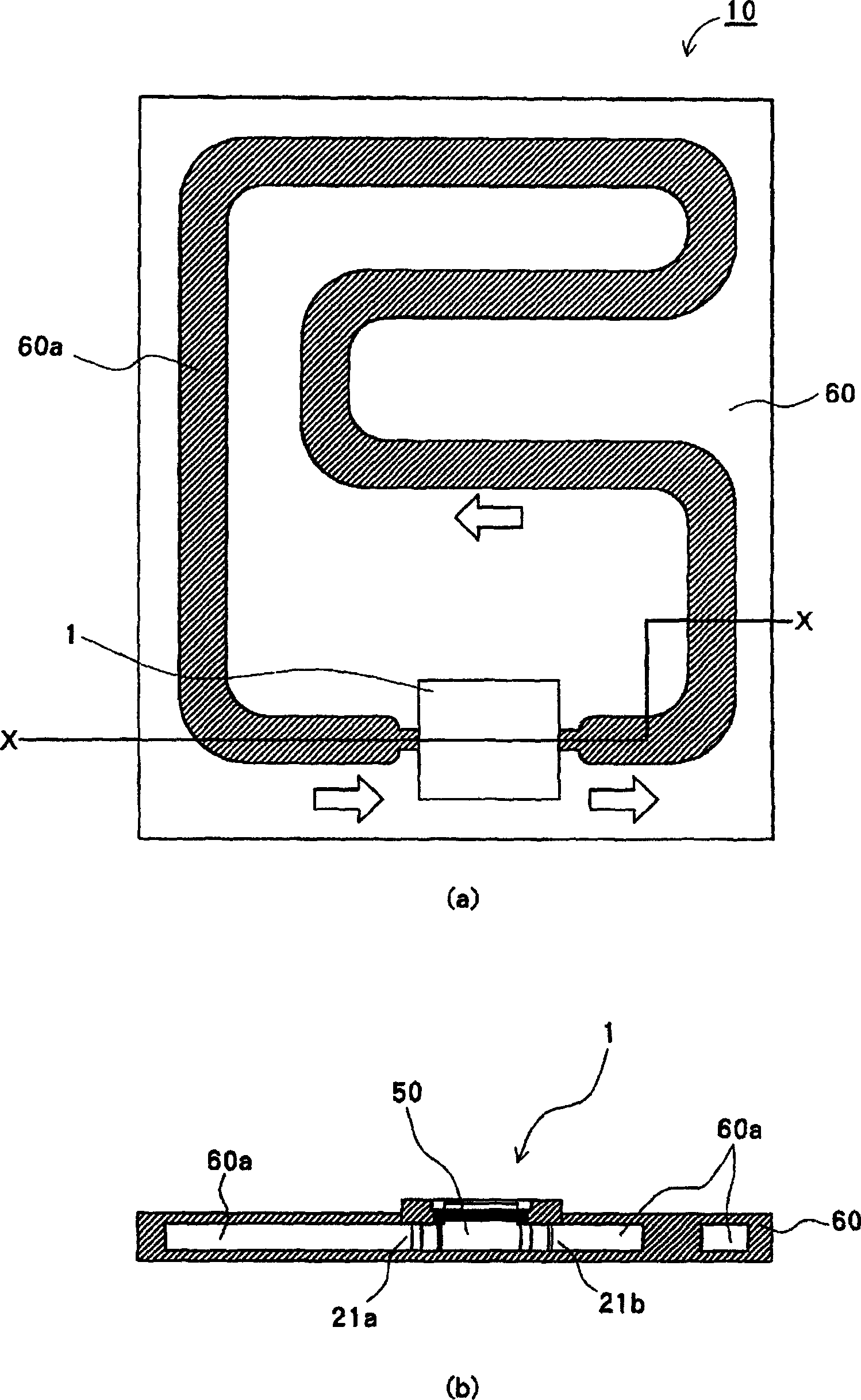
[0039] figure 1 showing a schematic view of a cooling system provided with a piezoelectric pump according to a first embodiment of the present invention, figure 1 (a) is a plan view of the liquid flow path in the cooling system, while figure 1 (b) is along figure 1 (a) Cross-sectional view of midline X-X.
[0040] figure 1 The illustrated cooling system 10 is a water-cooled cooling device, preferably used to provide cooling for electronic equipment, such as portable personal computers. The cooling system 10 is generally provided with a flow channel unit 60, in which a circulating flow channel 60a and a piezoelectric pump 1 connected to the flow channel unit 60 are formed, and used for circulating the liquid in the flow channel. The flow channel unit 60 and the piezoelectric pump 1 provide a flow channel of a closed structure. Inside the runner, it is filled with circulating liquid.
[0041] In the flow channel unit 60, circulation flow channels 60a are formed in a p...
no. 2 example
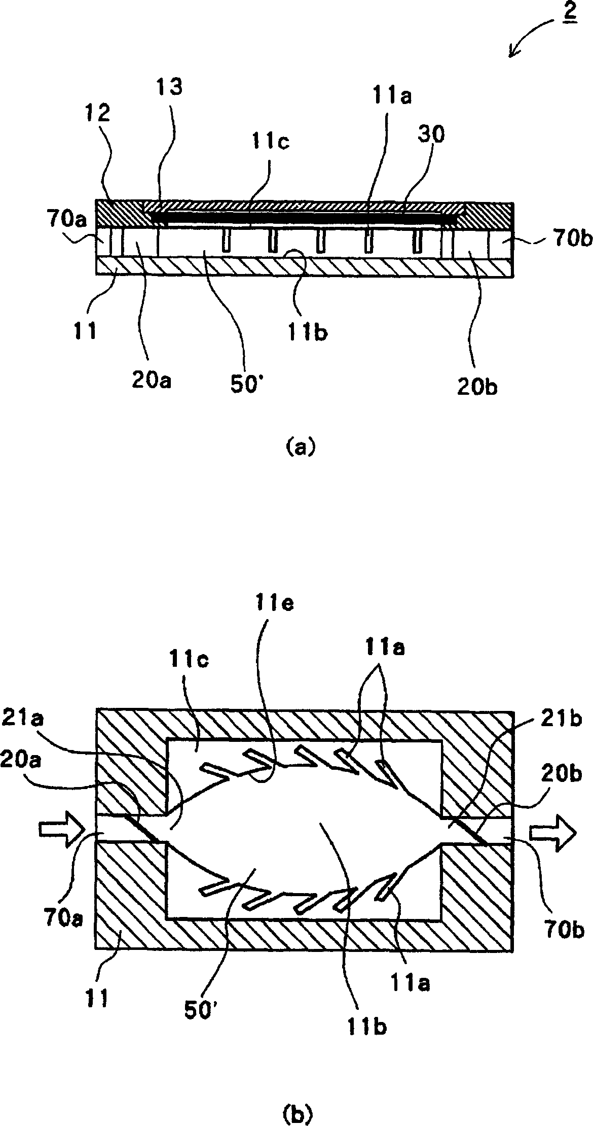
[0059] In the first embodiment, the pressure chamber is formed in a rectangular parallelepiped shape, however, the pressure chamber may be formed such that the cross-sectional area gradually changes in order to reduce the resistance of the liquid.
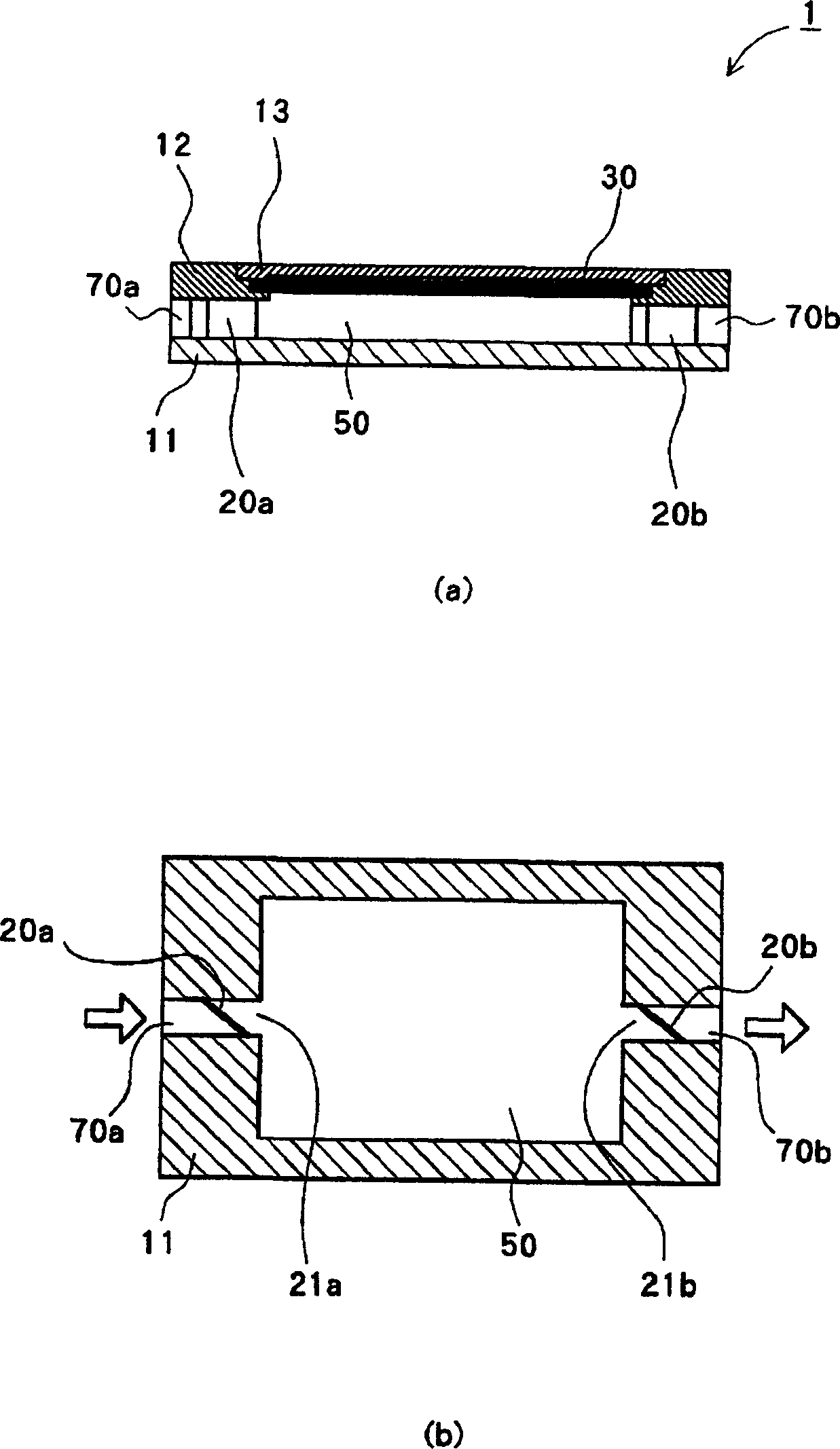
[0060] image 3 A piezoelectric pump according to a second embodiment of the present invention is shown. image 3The piezoelectric pump 2 shown in is formed such that the pressure chamber 50' is formed into a streamlined shape. On the peripheral wall of the pressure chamber 50', means for accelerating the flow of the liquid (return groove 11a) are distributed. other structures with figure 2 The structure of the piezoelectric pump 1 shown in is the same, the same reference numerals are applied to components having the same functions, and explanations thereof are omitted.
[0061] image 3 The pressure chamber 50' shown in (b) is provided with a substantially streamlined peripheral wall surface 11e viewed from the upper surface....
no. 3 example
[0071] usually, figure 1 The closed structure flow channels in the cooling system 10 shown in are filled with liquid so that no air bubbles can be trapped. But, for example, there are cases where dissolved oxygen changes into bubbles and the bubbles mix into the liquid. In piezoelectric pumps, the presence of air bubbles inside the flow channel can reduce the efficiency of the pump. Moreover, the presence of air bubbles in the interior of the flow channel of the closed structure will reduce the cooling efficiency of the cooling system 10 .
[0072] Therefore, in order to further improve the efficiency of the pump, in addition to the above two embodiments, the piezoelectric pump may be provided with means for collecting air bubbles mixed in the liquid.
[0073] Figure 7 to Figure 9 The corresponding piezoelectric pumps 3, 3', 3" shown in are provided with gas chambers 35, 35', 35". Figure 7 (a), 8(a) and 9(a) are side sectional views of piezoelectric pumps 3, 3', 3", F...
PUM
 Abstract
Description
Claims
Application Information