
Marking buoy device using a wave-force generation to emit light by converting wave force to electric energy

A technology indicating buoys and wave power, applied in buoys, ocean power generation, motor vehicles, etc., can solve the problems of wave size and frequency that cannot be kept uniform, and achieve good effects

Inactive Publication Date: 2006-09-20
车奉烈
View PDF0 Cites 7 Cited by
  • Summary
  • Abstract
  • Description
  • Claims
  • Application Information

AI Technical Summary

Problems solved by technology

[0004] However, the size and frequency of waves at sea cannot be kept uniform, and always vary greatly with regions and seasons

Method used


Image

  • Marking buoy device using a wave-force generation to emit light by converting wave force to electric energy
  • Marking buoy device using a wave-force generation to emit light by converting wave force to electric energy
  • Marking buoy device using a wave-force generation to emit light by converting wave force to electric energy

Examples


Embodiment 1

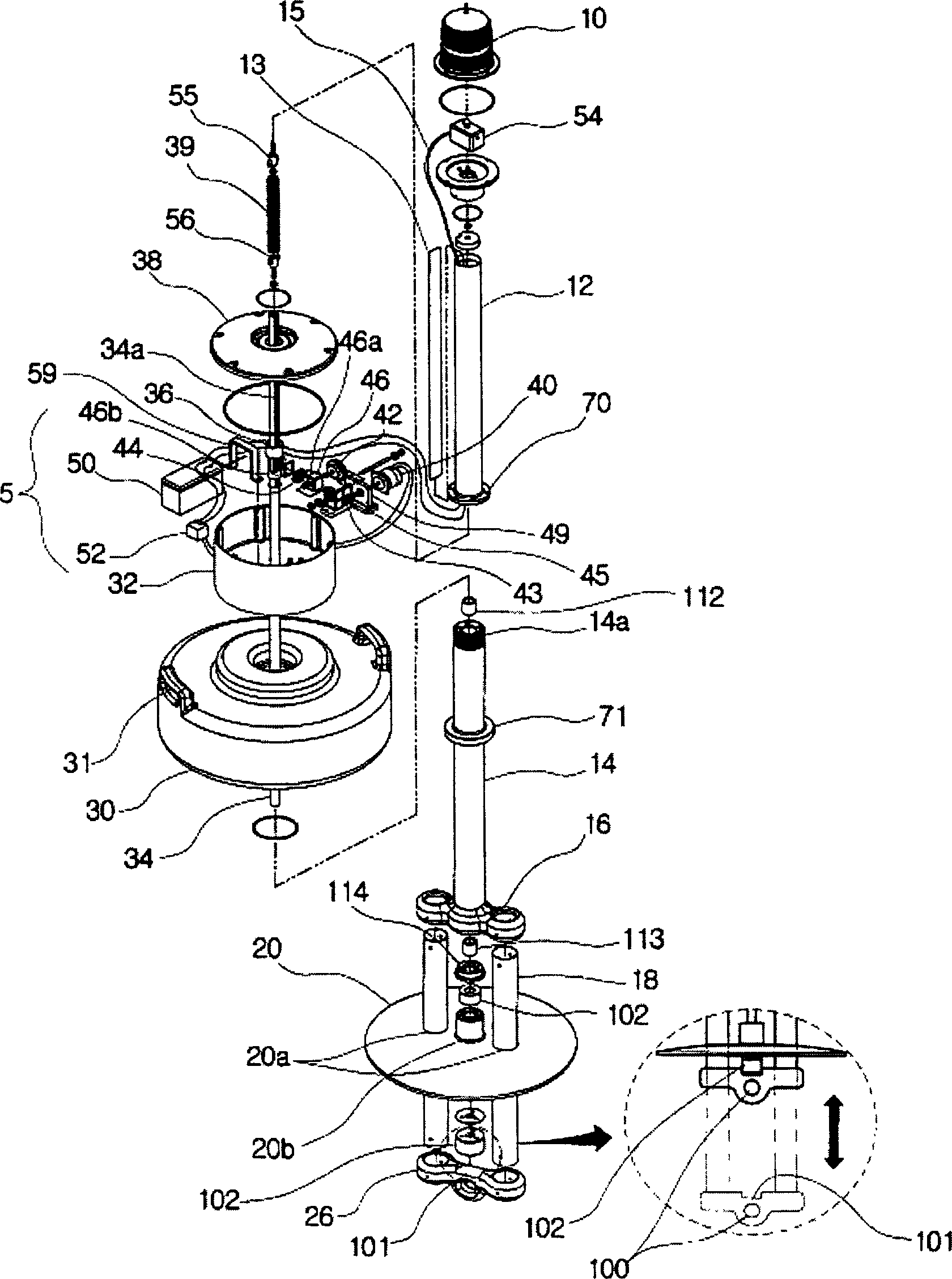
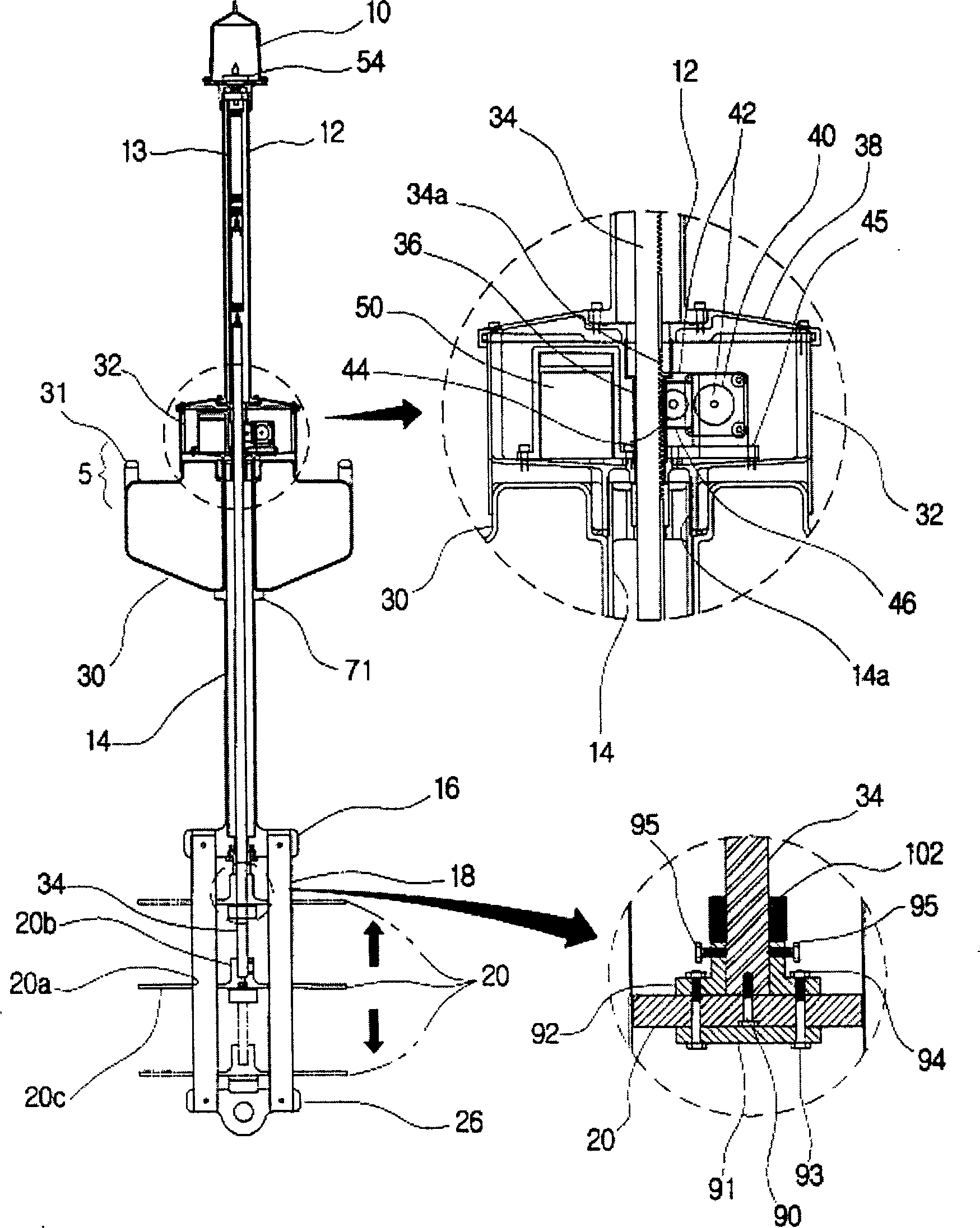
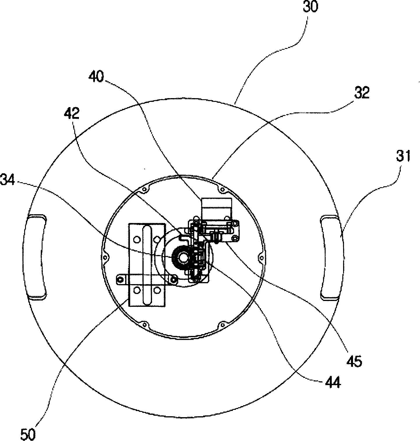
[0045] figure 1 It is a schematic diagram showing the decomposition of Embodiment 1 of the present invention one by one, Figure 2a and 2b yes figure 1 Front view and top view of the structure after assembly of the middle parts, Figure 2c It is an enlarged view of the gear box at the middle part of the present invention.

[0046] The present invention provides an indicating buoy device which utilizes the wave power of waves to generate electricity, and makes the indicator light 10 emit light while the battery 50 is storing electricity. The indicator light 10 is a lamp using direct current and equipped with a reflector. The battery 50 only needs DC 1.5V~DC 24V power, among which DC 12V is the best value to use, and if it is used for ship indication, DC 24V is enough. In the present invention, the upper and lower support rods 12, 14 are vertically combined with the guide column 18. The upper support rod 12 is combined with the upper end indicator lamp 10 using a support me...

Embodiment 2

[0076] Figure 11 is a schematic diagram of an exploded structure of another embodiment of the present invention, Figure 12a and 12b yes Figure 10 The front view and top view of the structure in the assembled state, Figure 12c yes Figure 10 The partially enlarged exploded schematic diagram of the middle gear box, as one of the proposals of the present invention, the above-mentioned buoyancy assembly 5 includes a gear box 62 on the float, and small boxes 36, 46 are used in the gear box 62 to maintain airtightness. Therefore the appearance of the float 60 and the gearbox 62 will be slightly different. like Figure 12a The gear box 62 is placed in the float 60, so that the center of gravity of the overall weight is lowered, which is conducive to maintaining the vertical state of the mechanism. The main electrical components such as the generator 40 and the battery 50 are close to seawater, which is not conducive to airtightness.

[0077] even as above Figure 11 The co...


PUM


Abstract

A mark floating apparatus is provided to improve the efficiency, to excellently operate functions of main units in a rough sea-weather condition and to improve the durability by converting wave force to electric energy. A supporting member is combined with an upper and a lower supports and a pair of guide rodsvertically. A mark light is combined with the upper part of the upper support. A resistance plate moves the guide rods upward and downward by forming in a downward curvature. An operating device drives a generator by the vertical movement of a shaft and a floating to be combined with the resistance plate and charges a battery through a charging controller. A buoyancy member is a cylindrical shape to generate the buoyancy by combining with the middle of the supporting member. The buoyancy member stores the operating device in an additional space hermetically. A flickering controller operates the mark light in a preset flickering cycle by installing in the upper support. Thereby, a mark floating apparatus emits light by converting wave energy to electric energy.

Description

【Technical field】 [0001] The present invention relates to an indicating buoy device on the sea, in particular, the present invention relates to an indicating buoy device which converts wave energy into electric energy and emits light and utilizes wave power to generate electricity. 【Background technique】 [0002] The usual indicator buoys are light-emitting devices at sea at night. They are mainly used to guide safe waterways for ships and prevent accidents of various ships carrying people and goods. In addition, they can also be used for reducing fishery resources in offshore areas Fishermen, who depend on marine resources, indicate where their nets are, so the demand is increasing every year. [0003] But if the light-emitting power supply of the indicator light of this indicating part only depends on the battery, not only will the battery be replaced frequently, but also the maintenance of the battery will be very thorough. So it is very difficult in practicality and in ...

Claims


Application Information

Patent Timeline
Patent Type & Authority Applications(China)
IPC IPC(8): B63B22/16B63C7/26F03B13/18
CPCY02E10/38F03B13/1855B63B2021/225B63B22/166B63C7/26F03B13/1845Y02E10/30B63B22/16
Inventor 车奉烈
Owner 车奉烈
Learn More