Pulse charging an electrochemical device

An inductance and current technology, used in electroplating and electrochemical conversion technology, which can solve problems such as short current pulses

Inactive Publication Date: 2006-09-20
UNIVERSITY OF LEICESTER
View PDF0 Cites 30 Cited by
  • Summary
  • Abstract
  • Description
  • Claims
  • Application Information

AI Technical Summary

Problems solved by technology

[0005] The problem of obtaining these very short and large amplitude current pulses is solved by implementing the power electronic converter of the present invention typically utilizing resonant technology

Method used


Image

  • Pulse charging an electrochemical device
  • Pulse charging an electrochemical device
  • Pulse charging an electrochemical device

Examples


Embodiment Construction

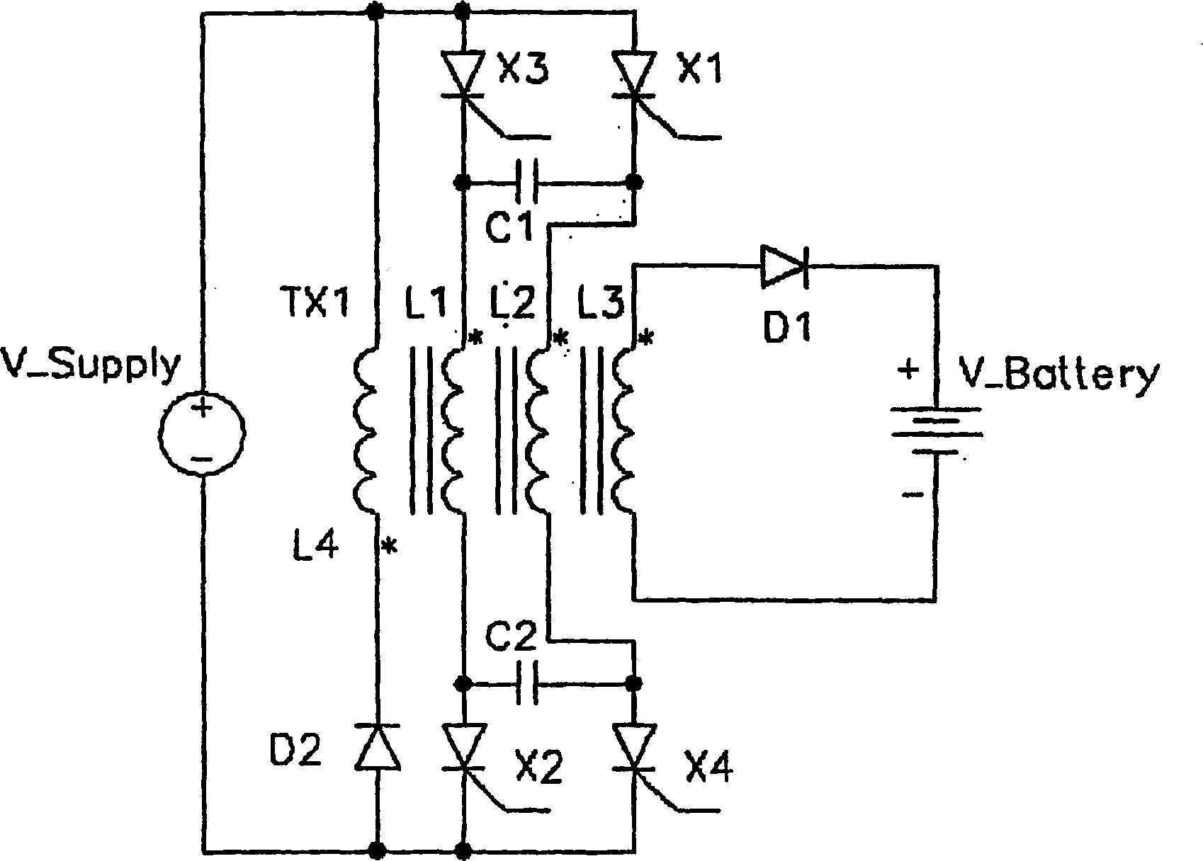
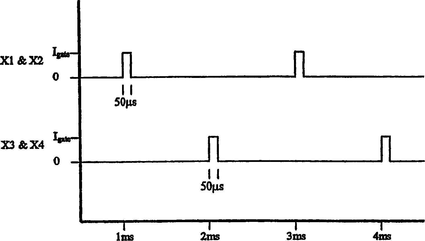
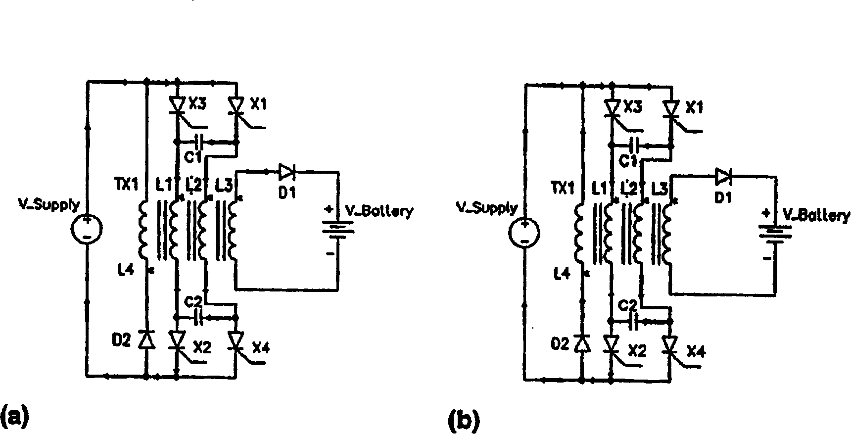
[0041] Figures 1a to 2 f shows a first preferred embodiment of the invention. The circuit shown in these figures comprises a transformer TX1 with four separate coils L1, L2, L3 and L4. L1 is connected to the DC supply voltage via two thyristors X2 and X3 at both ends of the coil. L2 is likewise connected to the DC supply voltage via two thyristors X1 and X4. For example, the first ends of the L1 and L2 coils, starting ends (use * to mark) are connected together through a capacitor C1, and the other ends of the L1 and L2 coils are connected together through a second capacitor C2. The anodes of the thyristors X1 and X3 are connected to the positive terminal of the DC power supply, and the cathodes of X2 and X4 are connected to the negative terminal of the DC power supply. The gates of the thyristors X1, X2, X3 and X4 are controlled by a conventional pulse generator (not shown). A typical firing pulse for the gates of thyristors X1, X2, X3 and X4 is given by Figure 1b sho...


PUM


Abstract

A system and method for producing electrochemical conversion in an electrochemical device comprises a power converter, for example, a resonant circuit, connected to the electrochemical device and a triggering circuit connected to the power converter. The triggering circuit comprises a pulse generator to trigger the power converter to generate positive pulses of current for passing through the electrochemical device causing electrochemical conversion in the electrochemical device.

Description

technical field [0001] The present invention relates to the field of battery charging, and more generally to any electrochemical conversion technique, such as electroplating. Background technique [0002] Traditional charging methods for lead-acid batteries use a constant current, constant voltage charging algorithm, where a constant current is supplied to the battery until the terminal voltage reaches a preset limit, and then charging continues at a constant voltage. Therefore, it can take several hours to fully charge, or sacrifice a large amount of electrolyte to speed up the process. In contrast, applying pulse charging technology has been shown to significantly reduce the time it takes to fully charge without compromising battery life. [0003] Conventional pulse charging schemes utilize a typical sequence of pulse current ratios of 100 ms charging ("on") time followed by a stabilization time ("off") of 100 ms to 300 ms. However, charge reception has been found to be ...

Claims


Application Information

Patent Timeline
Patent Type & Authority Applications(China)
IPC IPC(8): H02J7/00H01M6/06H01M6/50H01M10/06H01M10/42H01M10/44H02M3/335
CPCY02E60/12H02J7/0052Y02B70/1433H01M6/06H01M10/06H02J7/0093H02M3/33569H01M10/4257H01M6/5088H02J2007/0059H01M10/44H02J2207/20H02J7/00711Y02B70/10Y02E60/10H02M3/33573H02M3/01H02J7/00Y02B40/00
Inventor 保罗·威廉·勒弗利乔纳森·彼得·斯塔基
Owner UNIVERSITY OF LEICESTER
Why Eureka
Try Eureka