Pulse battery charger methods and systems for improved charging of batteries

Inactive Publication Date: 2014-12-25
EVGENTECH
View PDF5 Cites 25 Cited by
  • Summary
  • Abstract
  • Description
  • Claims
  • Application Information

AI Technical Summary

Benefits of technology

[0023]The present invention comprises charging methodology that allows battery cells, such as Li-ion, to be charged using high effective charging rates during substantially the entire charging process. Still further, the present invention comprises methods and battery charging systems suitable for providing such charging methods wherein a plurality of charging pulses is applied to a battery at an average rate of at least about 1C or greater, wherein the plurality of instantaneous open circuit voltages (OCVinst) existing during the charging process substantially remain below Vmax for substantially

Problems solved by technology

Inadequacy of battery charging processes, especially in lithium ion (“Li-ion”) batteries, is a critical problem today.
Generally speaking, while the construction of and chemical aspects of Li-ion batteries have progressed significantly since their market introduction in the early 1990's, the methods used to charge them have not changed markedly.
If the Li-ion cell exceeds its rated Vmax, dangerous conditions may result or, at a minimum, the battery may quickly fail.
Maintaining the cell at constant voltage necessarily results in significant reduction in the Li-ion battery charging rate.
Somewhat counterintuitively, increasing the current does not greatly hasten attainment of the full % SOC.
While the device software often indicates that the battery is at about 100% charge in about an hour, users do not actually obtain full capacity in this time, and the user will experience the need to recharge their device more frequently due to the battery having only partial capacity.
Such requirements restrict the ability to use faster charging Li-ion batteries.
Accordingly, fast charging is not readily available to users of mobile devices today and users must choose to either charge their batteries for longer times to enable longer periods of use or they must charge their batteries frequently and lose mobility.
These high rate Li-ion “power” batteries are capable of accepting charge at a higher rate than their “energy” battery counterparts, however, the trade-off for this higher charging rate is lower energy density and higher cost.
However, for most EV battery packs, Level 2 charging will take four or more hours to achieve significant SOC/vehicle range from a single charging event.
However, much confusion exists in regard to EV fast charging times today because there is no universally agreed-to protocol to measure charging performance or to describe battery capacity.
As stated in Tesla Motors marketing literature: “It's somewhat like turning down a faucet to fill a glass to the top without spilling.” Put another way, while Tesla Motors' SuperCharger stations can supply the necessary power to fully charge the battery pack in about 40 minutes, the voltage response that invariably results from application of a high constant charging current does not allow the battery to be charged to 100% SOC unless the charging

Method used


Image

  • Pulse battery charger methods and systems for improved charging of batteries
  • Pulse battery charger methods and systems for improved charging of batteries
  • Pulse battery charger methods and systems for improved charging of batteries

Examples


example 1

[0140]A new 3.7 V 1150 mAH lithium ion “energy” cell for use in mobile devices configured with no protection circuit (Tenergy 503565, Allcell.com) was discharged to 3.0 V at 0.2 V using the off-the-shelf charger / discharger. The discharged cell was connected to the inventive circuit and current sufficient to supply a 1C charge was applied until cell OCVinst reached 4.2V, at which time the current was terminated. The cell was touched periodically during the charging process, and no rise in temperature was noted.

[0141]As shown in FIG. 12, the cell charged for approximately 1 hour at 1C without OCVinst exceeding Vmax. As discussed previously, this OCVinst represents the voltage reading during the OFF-time (i.e., when no charge pulse is applied).

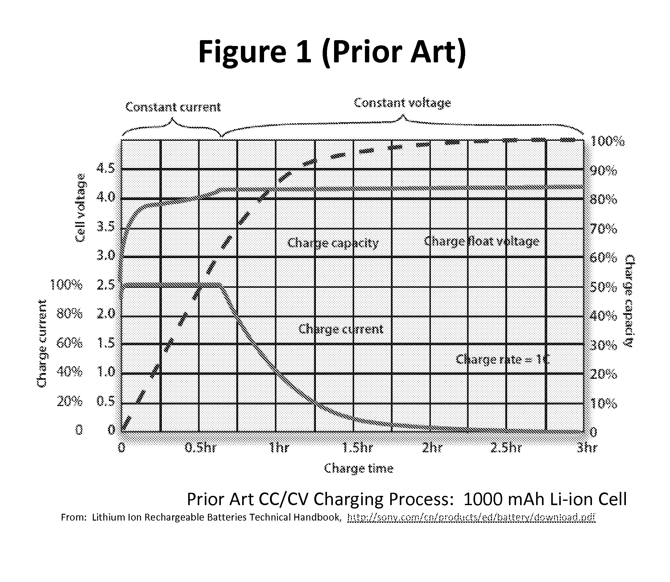
[0142]The voltage response resulting from application of the inventive charging process to the Li-ion cell is markedly different from that resulting from the representative prior art 1C constant DC current applied to a similar mobile device-type ...

example 2

[0145]A new 3.7V 250 mAH lithium ion “power” cell for use in a radio controlled (“RC”) helicopter (Heli-Max®, Amazon.com) with the protection circuit removed was discharged to 3.0 V at 0.2C. The inventive circuit was used to charge the cell at 4C until OCVinst reached 4.2V. The cell was touched periodically during the charging process and no significant increase in temperature was noted.

[0146]As shown in FIG. 13, when charged at 4C, the voltage rise over the course of the charging process was gradual. This result shows that the inventive charging process allows an RC-type cell, which in large respects mirrors the charge / discharge behavior of a Li-ion cell used in EV cell packs, to be charged at a high rate to 100% capacity.

[0147]The offset voltage for this charging process, that is the voltage applied in each pulse in relation to measured OCVinst, was consistently about 250 mV throughout the charging process. The higher offset voltage with this cell is thought to be a result of the ...

example 3

Prophetic

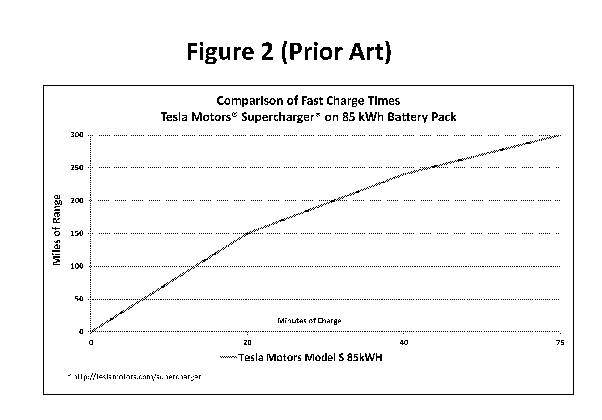
[0149]Tesla Motors® has recently introduced a DC fast charging infrastructure on interstate highways in the US. Tesla Motors has reported that the Model S 85 kWh battery, which has an approximately 300 mile range at 100% SOC, can be charged to 50% in 20 minutes, 80% in 40 minutes, and 100% in 75 minutes using the company's SuperCharger charging system. This translates to an about 1.5C charging for the first 50% SOC, about 0.9C for the next 20 minutes and about 0.34C for the final 35 minutes. It can then be inferred that the reduction in charging rate seen after 20 minutes, and the more marked reduction after 40 minutes results from the characteristic voltage rise from this prior art fast charging process.

[0150]As disclosed herein, the inventive charging process substantially does not cause the characteristic voltage rise seen with conventional DC fast charging. In a prophetic example, the inventive charging process could reduce the time to charge the Tesla Model S 85 kWh to...


PUM


Abstract

The inventions herein relate to devices and methods to impart charge to battery cells. Still further, the present invention incorporates to pulse charging methods and systems related thereto that provide improvements in charging speed, efficiency and additional benefits.

Description

CROSS REFERENCE TO RELATED APPLICATIONS[0001]This application is a continuation-in-part of U.S. Utility application Ser. No. 14 / 210,101, filed Mar. 13, 2014, which application claims priority to U.S. Provisional Application No. 61 / 782,897, having a filing date of Mar. 14, 2013. These referenced applications are incorporated herein in their entireties by this reference.FIELD OF THE INVENTION[0002]The inventions herein relate to devices and methods to impart charge to batteries. Still further, the present invention incorporates pulse charging methods and systems related thereto that provide improvements in charging speed, efficiency and additional benefits.BACKGROUND OF THE INVENTION[0003]Inadequacy of battery charging processes, especially in lithium ion (“Li-ion”) batteries, is a critical problem today. Generally speaking, while the construction of and chemical aspects of Li-ion batteries have progressed significantly since their market introduction in the early 1990's, the methods ...

Claims


Application Information

Patent Timeline
IPC IPC(8): H02J7/00
CPCH02J7/0052H02J7/0093B60L3/003B60L3/0046B60L2240/36B60L2240/545B60L2240/547B60L2240/549B60L2240/80Y02T10/7072Y02T90/14B60L53/14B60L53/11B60L58/13B60L58/21B60L2200/10H02J7/00711H02J2310/48Y02T10/70Y02T90/12
Inventor HUNG, STEPHEN T.O'BRIEN, TIMOTHY J.
Owner EVGENTECH
Why Eureka
Try Eureka