Housing for mounting modulation and polarization components in alignment with an optical path

A housing, mounting plate technology, applied in the direction of image reproducers, projection devices, picture replicators, etc., using projection devices, which can solve alignment problems, do not anticipate or provide thermal deformation and stress birefringence, and seal the housing too much restraint and heat capacity and other issues, to achieve the effect of easy removal

Inactive Publication Date: 2006-09-20
MOXTEK INC
View PDF11 Cites 3 Cited by
  • Summary
  • Abstract
  • Description
  • Claims
  • Application Information

AI Technical Summary

Problems solved by technology

Also, the method of U.S. 2003/0117708 does not anticipate or provide a solution to thermal distortion and stress birefringence that may arise in a high thermal environment due to excessive confinement and heat capacity in the sealed enclosure
[0017] It can thus be seen that

Method used


Image

  • Housing for mounting modulation and polarization components in alignment with an optical path
  • Housing for mounting modulation and polarization components in alignment with an optical path
  • Housing for mounting modulation and polarization components in alignment with an optical path

Examples


Example Embodiment

[0038] This description relates in particular to such elements which form part of the device according to the invention or which directly cooperate with it. It should be understood that elements not specifically shown or described may have various forms well known to those skilled in the art.
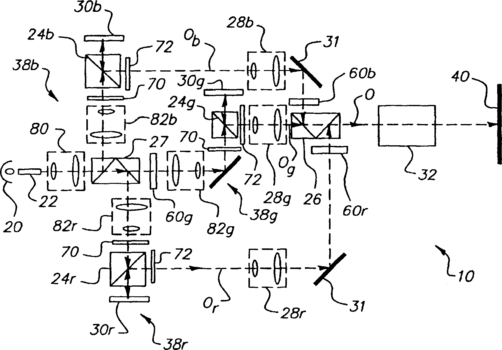
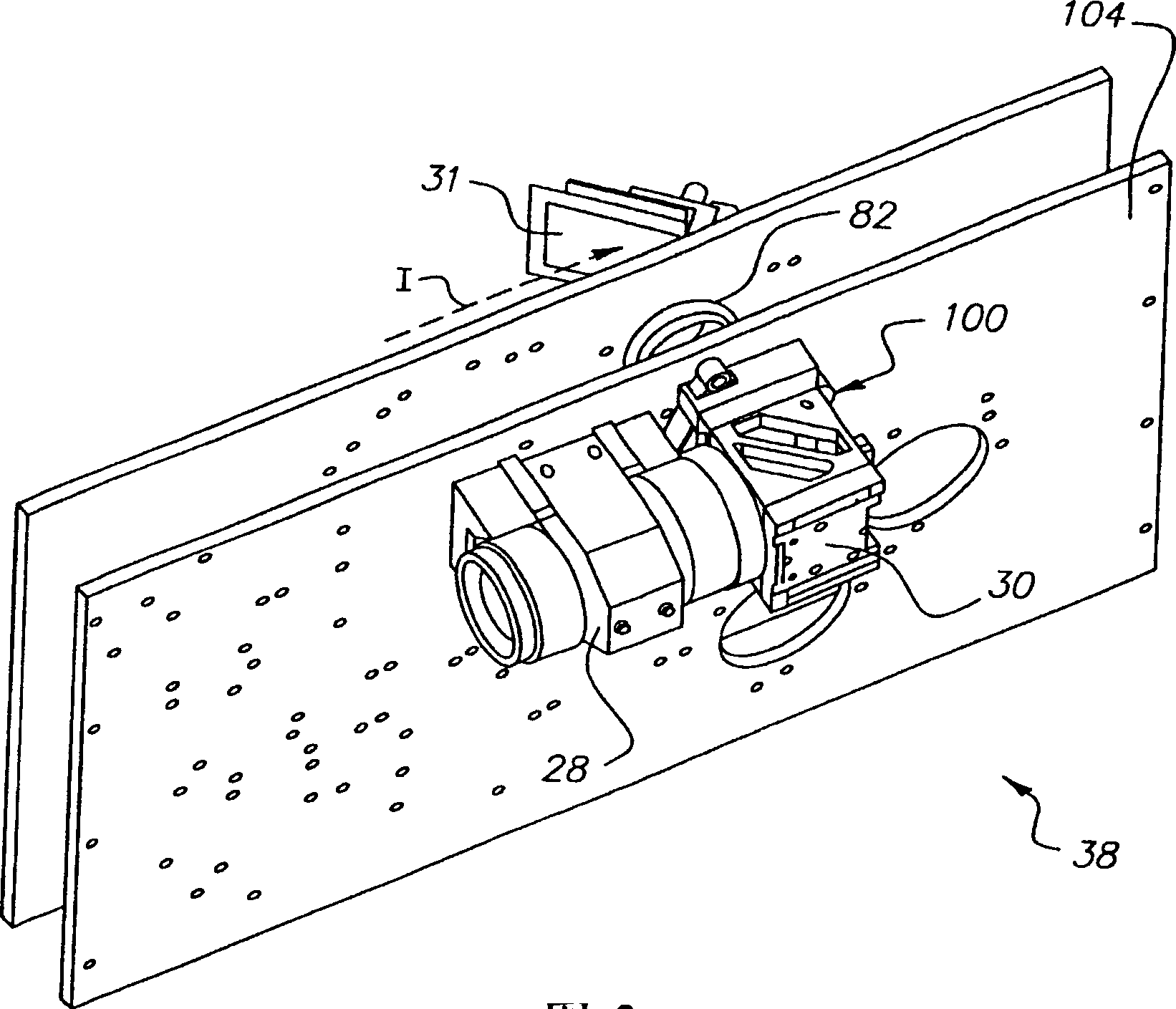
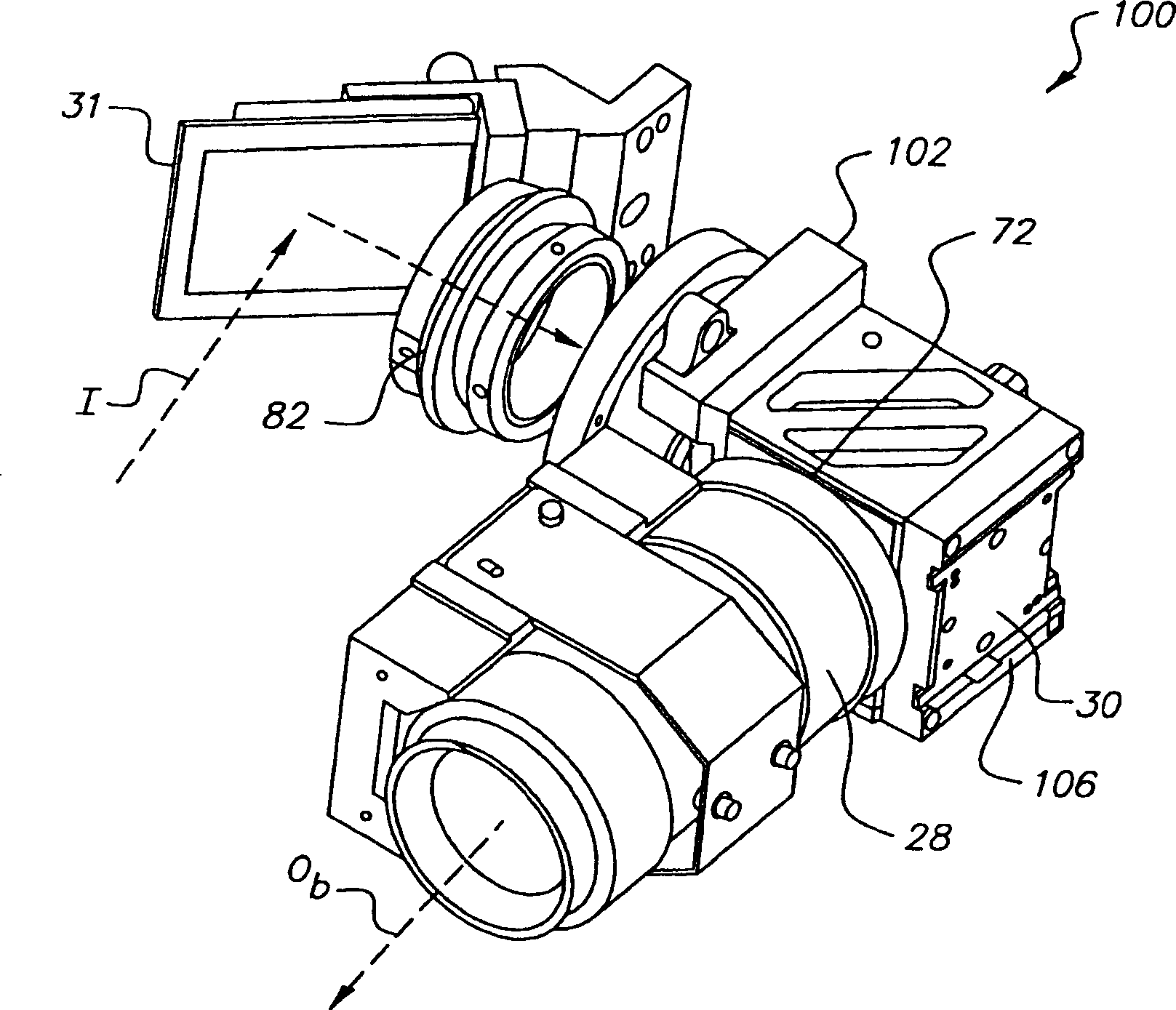
[0039] reference figure 2 with 3 , Shows a perspective view of the housing 100, which is used to install the spatial light modulator 30 and its supporting polarization element on the rack wall 104 inside the projection device 10, and the polarization supporting element is used for the monochromatic modulation channel. In the preferred embodiment, it is the blue channel. The monochromatic illumination I is led to the rotating mirror 31, and the reflected illumination I passes through the magnifying relay lens 82 and the annular hole 102, and then enters the housing 100. Such as figure 1 Shown, and then along O b The modulated light output from the axis is introduced into a reduction relay ...


PUM


Abstract

A housing (100) for mounting a wire grid polarizing beamsplitter (122) and a spatial light modulator (30) in alignment with an output optical path comprises a front plate having an opening for admitting incident illumination provided along an illumination axis. A modulator mounting plate (110) is spaced apart from and parallel to the front plate, for mounting the spatial light modulator in the optical output path of the illumination axis. First and second polarizer support plates are spaced apart from each other and extend between the front plate and the modulator mounting plate. The respective facing inner surfaces of the first and second support plates provide coplanar support features for supporting the wire grid polarizing beamsplitter between the inner surfaces. The wire grid polarizing beamsplitter extends between the facing inner surfaces. The surface of the wire grid polarizing beamsplitter is a fixed angle with respect to the surface of the spatial light modulator on the modulator mounting plate. The fixed angle defining an output optical axis along the output optical path.

Description

technical field [0001] The present invention relates generally to digital imaging devices, and more particularly to frames and methods for mounting polarizing elements and reflective LCD spatial light modulators. Background technique [0002] Digital color projectors, originally introduced as small-scale imaging devices for the commercial display market, have steadily improved overall imaging performance and light output capability. However, there are still a number of significant technical hurdles for digital cinema projectors to compete with conventional film film projectors such as those used in theaters. Unlike conventional movie projectors, high-quality digital projector systems provide separate color modulation paths for red, green, and blue (RGB) image data. To project a full color image, the design of digital color projection equipment requires combining the monochromatic light beams with proper intensity and registration for carrying the image formed on each monoch...

Claims


Application Information

Patent Timeline
IPC IPC(8): H04N9/31G03B21/14
CPCG03B21/14G03B21/005G03B21/145G03B21/2073
Inventor F·D·埃尔纳B·D·西尔弗斯坦
Owner MOXTEK INC
Why Eureka
Try Eureka