Surface light source device

A surface light source and optical waveguide technology, applied in the field of surface light source devices, can solve the problems of increasing cost and increasing point light sources, etc.

Inactive Publication Date: 2006-09-27
TOMOEGAWA PAPER CO LTD
View PDF0 Cites 11 Cited by
  • Summary
  • Abstract
  • Description
  • Claims
  • Application Information

AI Technical Summary

Problems solved by technology

However, increasing the number of point light sources creates a problem of increasing cost

Method used


Image

  • Surface light source device
  • Surface light source device
  • Surface light source device

Examples


Embodiment Construction

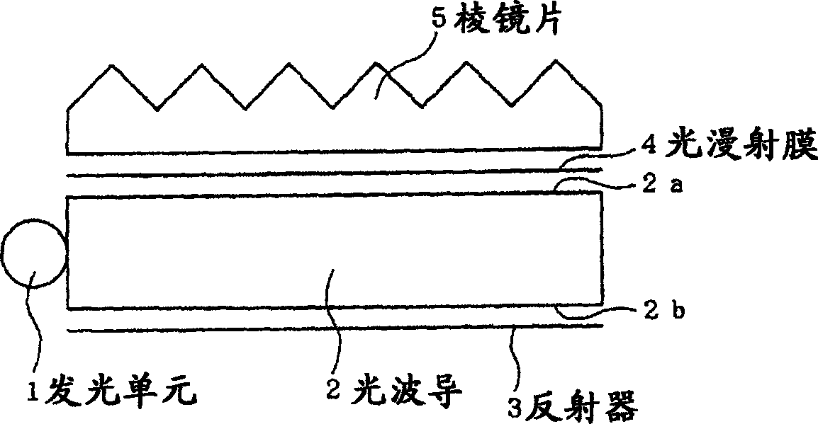
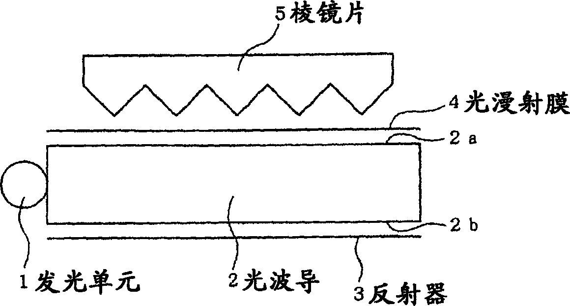
[0016] The invention will now be described in more detail with reference to the accompanying drawings. Figure 6 It is a schematic cross-sectional view of a surface light source device according to an embodiment of the present invention. The device has a light-emitting unit 11 composed of a point light source, an optical waveguide 12, and a reflector 13. And the prism sheet 15 of prism pattern. Figure 7 It is a schematic cross-sectional view of another embodiment of the surface light source device of the present invention. exist Figure 7 , by means of a light-diffusing adhesive layer 16, Figure 6 The directional light-diffusing film 14 of the mid-surface light source device is bonded to the light guide 12 . Figure 8 and Figure 9 It is a partial schematic sectional view of a surface light source device according to another embodiment of the present invention. exist Figure 8 and Figure 9 In , the prism pattern P is on the lower surface 12b of the optical waveguide ...


PUM

PropertyMeasurementUnit
diameteraaaaaaaaaa
diameteraaaaaaaaaa
diameteraaaaaaaaaa

Abstract

A surface light source device comprises a light emitting section ( 11 ) made of a single spot light source, a light guide plate ( 12 ), a reflective surface ( 13 ) provided on the back side of the light guide plate, and a prism pattern ( 15 ). On the light emitting surface side of the light guide plate ( 12 ), there is provided a directional light scattering film ( 14 ) consisting of at least two phases having different refractive indexes and scattering light when transmitting it. One phase of a larger refractive index includes a plenty of areas having a columnar structure extending in the thickness direction of a film and arranged to be perpendicular to a normal to the film, and exhibiting a maximum scattering angle of 10-40 DEG .

Description

technical field [0001] The present invention relates to a surface light source device, in particular to a surface light source device used as a backlight in an image display device, such as a liquid crystal display device or the like. Background technique [00021] A surface light source device is generally used in a liquid crystal display device to illuminate a display screen, for example, a liquid crystal display device. These surface light source devices generally include: a light emitting unit, an optical waveguide, a reflector, a prism sheet, and the like. A conventional surface light source device will now be described with reference to the accompanying drawings. figure 1 and figure 2 is a schematic cross-sectional view of an example of a conventional surface light source device, which includes: a light-emitting unit 1 , an optical waveguide 2 , a reflector 3 , a light-diffusing film 4 , and a prism sheet 5 . exist figure 1 In the surface light source device, the l...

Claims


Application Information

Patent Timeline
Patent Type & Authority Applications(China)
IPC IPC(8): F21V8/00G02F1/13357G02B5/02F21Y101/02G02B6/00G02F1/1335
CPCG02B6/0051G02B6/0038G02B6/0061G02F1/1335
Inventor 原田隆正北文雄
Owner TOMOEGAWA PAPER CO LTD
Why Eureka
Try Eureka