Fuel pump having plunger and fuel supply system using the same
A supply system, fuel pump technology, applied in the direction of the charging system, fuel injection pump, fuel injection device, etc., can solve the problem of fuel increase and other problems, to achieve the effect of reducing oil pressure
- Summary
- Abstract
- Description
- Claims
- Application Information
AI Technical Summary
Problems solved by technology
Method used
Image

Examples
no. 1 example
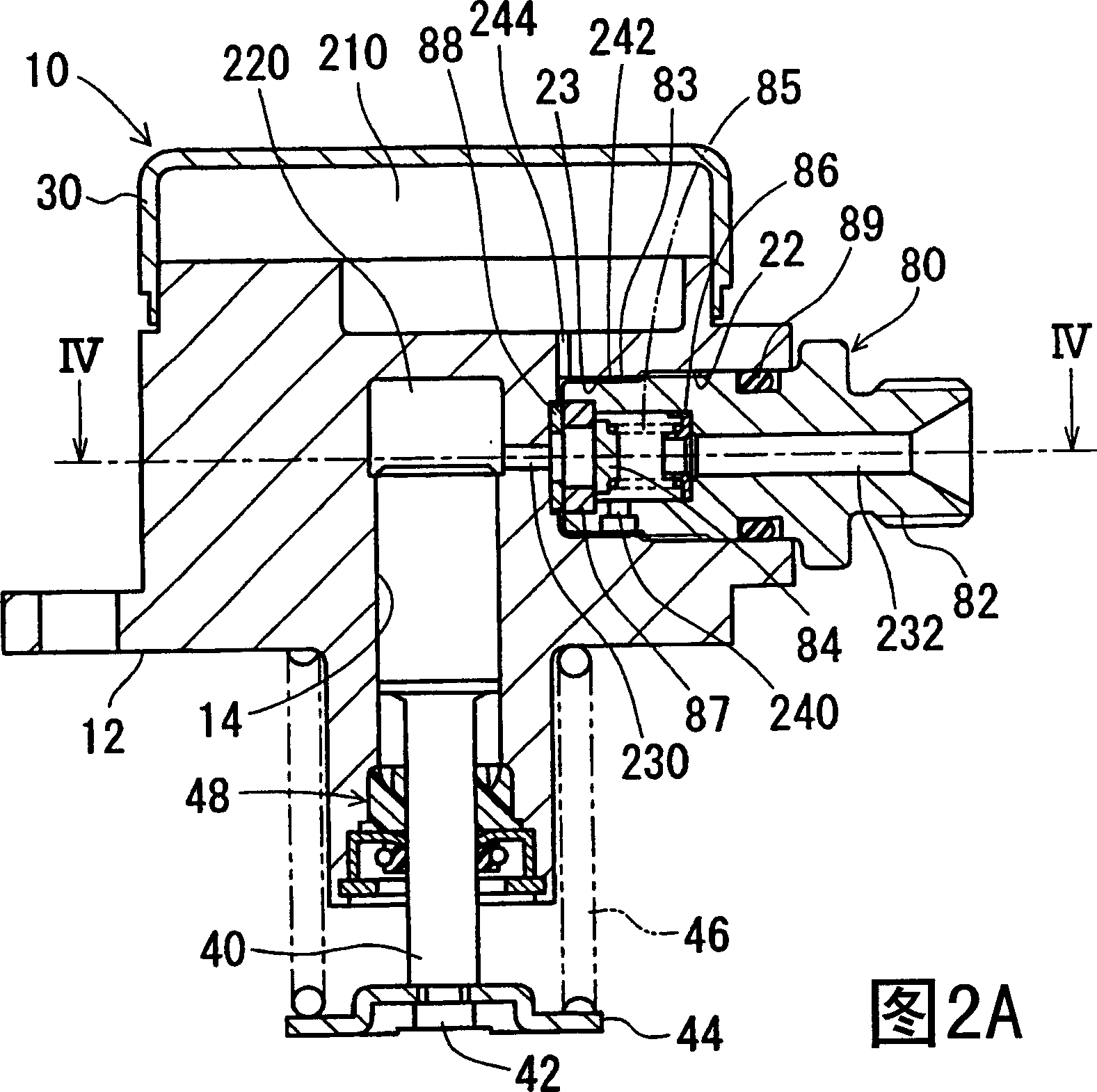
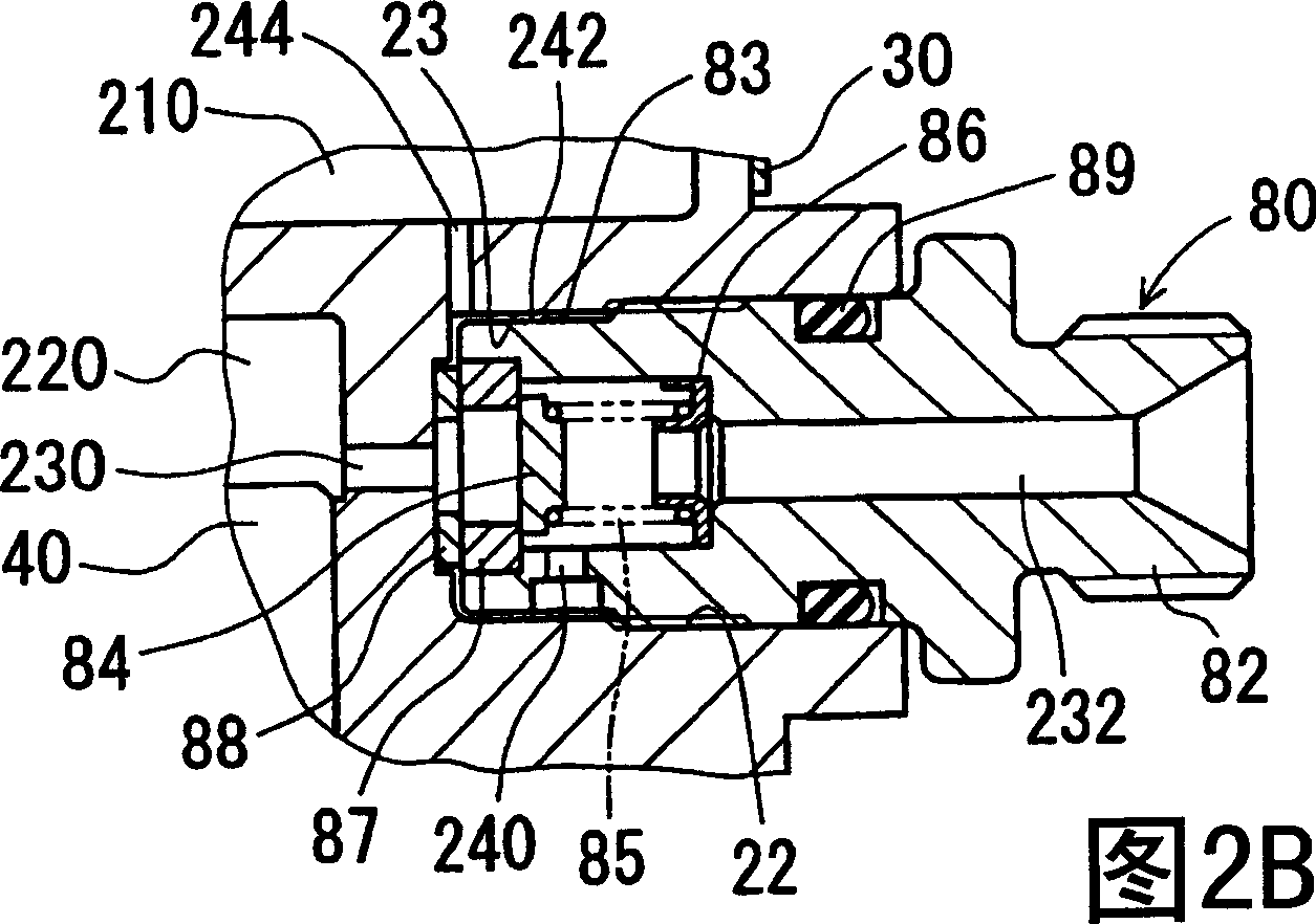
[0028] Refer to the attached figure 1 , 2A, 2B, 3 and 4 illustrate a first embodiment of the high-pressure fuel pump 10 . Figure 2A is along the Figure 4 View shown in midline IIA-IIA. image 3 is along Figure 4 View indicated by midline III-III.
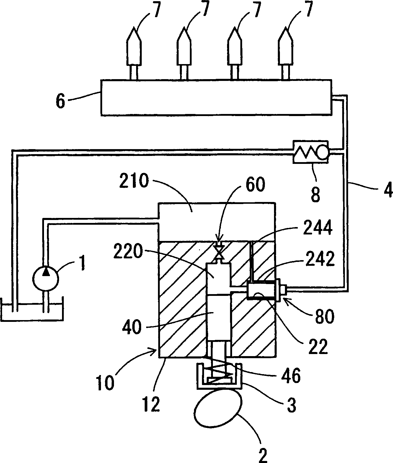
[0029] Such as figure 1 As shown, the fuel supply system includes a high-pressure fuel pump 10 . In addition, the fuel supply system is a direct-injection gasoline supply system that directly injects fuel into a cylinder block of a gasoline engine. The high-pressure fuel pump 10 supplies fuel to the fuel injection valve 7 .
[0030] The high-pressure fuel pump 10 uses an electromagnetically driven metering valve (solenoid valve) 60 to make and break communication between the suction chamber 210 and the compression chamber 220 . Fuel is supplied from the low-pressure fuel pump 1 to the suction chamber 210 . The plunger 40 reciprocates as the cam 2 rotates to pressurize the fuel sucked into the compression chamber 220 . The...
no. 2 example
[0059] Next, a second embodiment of the high-pressure fuel pump 90 will be described with reference to FIGS. 5A , 5B and 6 . Figure 5A is along the Figure 6 View shown at midline VA-VA.
[0060] In the second embodiment of the high pressure fuel pump 90 shown in FIGS. 5A , 5B and 6 , the pressure reducing valve 100 is mounted in the mounting hole 24 formed in the cylinder block 12 . In this structure, the pressure reducing valve 8 ( figure 1 ). The pressure reducing valve 100 restricts an abnormal rise in oil pressure on the downstream side of the high pressure fuel pump 90 . The pressure reducing valve 100 is one of the functional components of the high pressure fuel pump 90 .
[0061] The pressure reducing valve 100 includes a body 102 , a ball 104 , a guide element 105 , a spring 106 and a valve seat element 107 . The pressure reducing valve 100 is connected with the discharge channel 250 , wherein the discharge channel 250 communicates with the gap 242 . Internal th...
no. 3 example
[0068] Refer to the attached Figures 7 to 10 A third embodiment of the high-pressure fuel pump 110 will be described. Figure 7 is along Figure 8 View shown on midline VII-VII.
[0069] In the third embodiment of the high-pressure fuel pump 110, the outer peripheral surfaces 125, 135 of the valve seat members 124, 134 and the inner peripheral surfaces 23, 23, Between 25, small gaps 272, 284 are formed. The delivery valve 120 and the pressure reducing valve 130 are functional components of the high pressure fuel pump 110 . On the inner peripheral surfaces 23 , 25 of the mounting holes 22 , 24 , the oil discharge valve 120 and the pressure reducing valve 130 are installed.
[0070] Specifically, such as Figure 9 As shown, the valve seat member 124 of the oil delivery valve 120 is fitted on the outside of the end of the body 122 on the side of the discharge passage 230 so as to be coaxial with the body 122 . The delivery valve 120 defines a fuel outlet of the high pressu...
PUM
 Abstract
Description
Claims
Application Information
 - R&D
- Intellectual Property
- Life Sciences
- Materials
- Tech Scout
- Unparalleled Data Quality
- Higher Quality Content
- 60% Fewer Hallucinations
Browse by: Latest US Patents, China's latest patents, Technical Efficacy Thesaurus, Application Domain, Technology Topic, Popular Technical Reports.
© 2025 PatSnap. All rights reserved.Legal|Privacy policy|Modern Slavery Act Transparency Statement|Sitemap|About US| Contact US: help@patsnap.com