

Vertical orientation type liquid crystal display device
A liquid crystal display element, axis direction technology, applied in static indicators, nonlinear optics, optics, etc., can solve the problems of high contrast, insufficient, and inability to obtain the transmittance of liquid crystal display elements.
- Summary
- Abstract
- Description
- Claims
- Application Information
AI Technical Summary
Problems solved by technology
Method used
Image

Examples
Embodiment approach 1
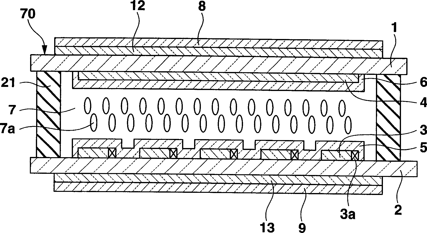
[0087] The liquid crystal display element of the present embodiment, such as figure 1 As shown, it includes: a pair of substrates 1, 2; pixel electrodes 3 and counter electrodes 4 formed on the inner surfaces facing each other; alignment films 5, 6 formed on the surfaces of these electrodes; A liquid crystal panel 70 composed of a liquid crystal layer 7 between the pair of substrates; a pair of polarizers 8, 9 arranged to sandwich the substrates on the outer sides of the pair of substrates 1, 2 of the liquid crystal panel 70; Two optical compensation layers 12 , 13 disposed between the pair of polarizers 8 , 9 on both sides of the liquid crystal panel 70 ; and a sealing material 21 for joining the pair of substrates 1 , 2 .
[0088] The substrates 1 and 2 are, for example, transparent substrates made of glass or the like, and are arranged to face each other with the liquid crystal layer 7 interposed therebetween.
[0089] The pixel electrode 3 and the counter electrode 4 are ...
Embodiment approach 2
[0126] In Embodiment 1 above, the liquid crystal display element in which the optical compensation plates 12 and 13 are arranged on both sides of the liquid crystal panel 70 is shown, but as Figure 5 As shown, another optical compensation plate 14 , 15 different from the optical compensation plates 12 , 13 is additionally arranged on both sides of the liquid crystal panel 70 respectively, and the purpose of the present invention can also be achieved. In this way, by arranging two other optical compensation plates 14 and 15 on both sides of the liquid crystal panel 70, the value of the retardation Rz in the Z direction can be made sufficiently large, and the viewing angle dependence of contrast can be sufficiently compensated. In the structure of the liquid crystal display element of the second embodiment, figure 1 In the liquid crystal display element of , except that another optical compensation layer 14, 15 is additionally arranged on both sides of the liquid crystal panel ...
Embodiment approach 3
[0137] In Embodiment 1 above, the liquid crystal display element in which the optical compensation plates 12 and 13 are arranged on both sides of the liquid crystal panel was shown, but the present invention is not limited thereto. figure 1 Among them, the optical compensation element 13 on the side opposite to the viewing side of the liquid crystal panel 70 may be replaced with another optical compensation layer (optical compensation plate 16 ) having different optical characteristics. The structure of the liquid crystal display element of Embodiment 3 is the same as that of Embodiment 1 except that one optical compensation layer arranged on one side of the liquid crystal panel 70 is replaced with another optical compensation layer having different optical properties. The same reference numerals are attached to the same components, and explanations thereof are omitted.
[0138] The liquid crystal display element of this embodiment, such as Figure 7 As shown, it includes: a ...
PUM
 Abstract
Description
Claims
Application Information