Self-compensating laser tracker

A laser tracker and self-compensation technology, applied in the direction of instruments, optics, optical components, etc., can solve problems such as cost

Inactive Publication Date: 2006-10-11
FARO TECH INC
View PDF2 Cites 24 Cited by
  • Summary
  • Abstract
  • Description
  • Claims
  • Application Information

AI Technical Summary

Problems solved by technology

These will take anywhere from a few minutes to one or more hours, depending on the specific tracker and required tests
In most cases, while mechanical vibration is also a significant cause of loss of tracker accuracy, the main cause is thermal drift, so new methods of compensating for CMMs are needed

Method used


Image

  • Self-compensating laser tracker
  • Self-compensating laser tracker

Examples


Embodiment Construction

[0011] Reference will now be made in detail to the exemplary embodiments, examples of which are illustrated in the accompanying drawings.

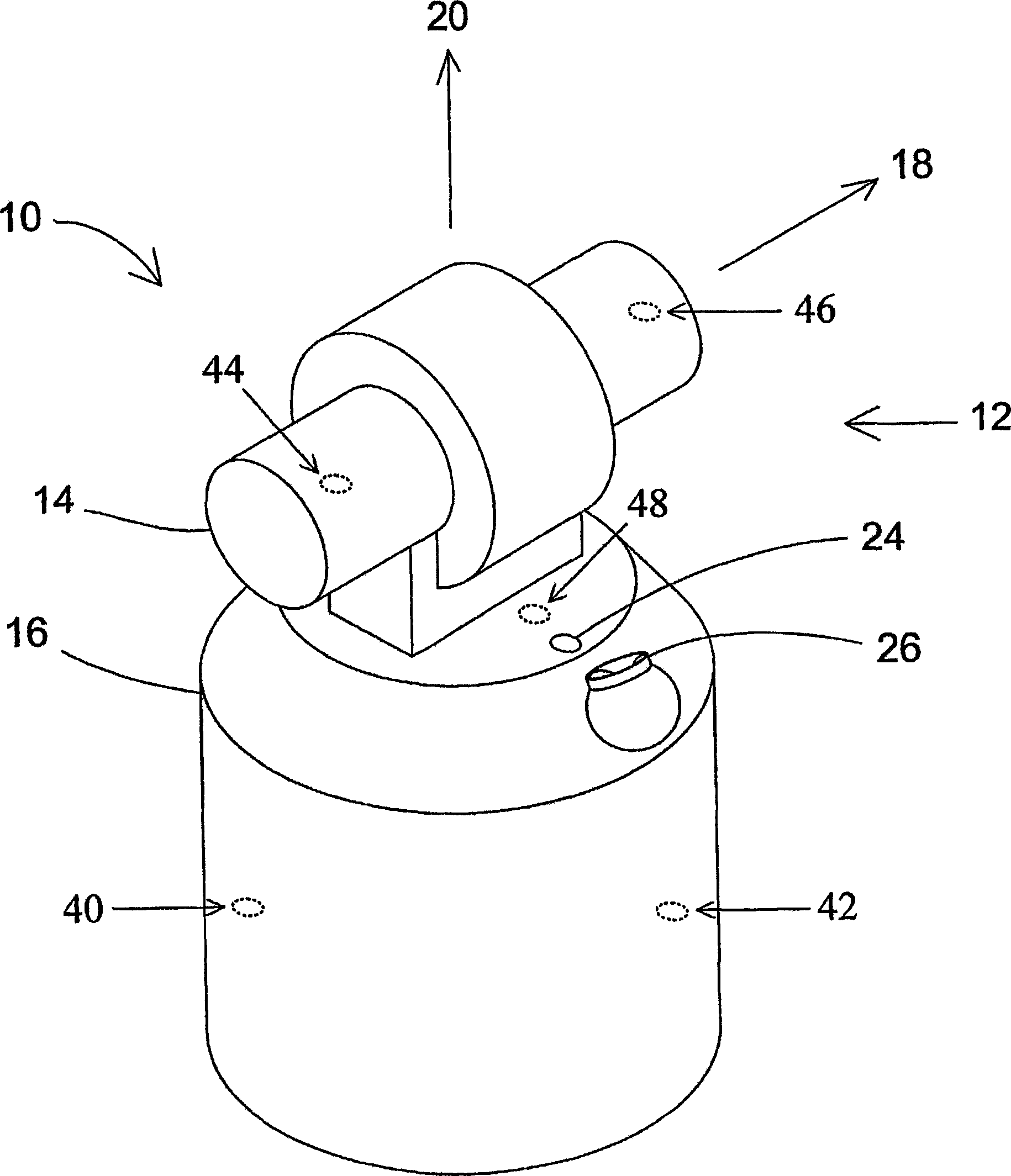
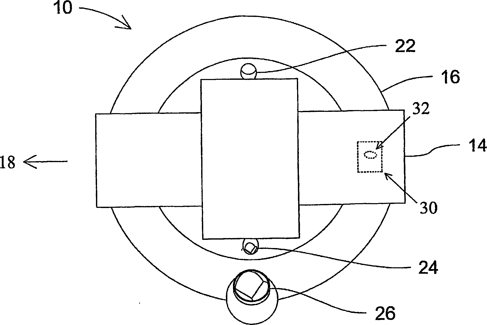
[0012] An exemplary gimbal beam steering mechanism 12 of the laser tracker 10 is as figure 1 As shown, it includes an apex rotation mount 14 mounted on an azimuth rotation base 16, and the apex and azimuth mechanical axes 18, 20 rotate to direct the laser beam in the desired direction. For clarity and simplicity, this type of gimbal mechanism 12 is used in the following discussion. However, other types of universal joints can also be used, and the techniques described here can be applied to these other types of universal joints as well.

[0013] Self-compensation with built-in tracker targets

[0014] An exemplary self-compensation method provides a method of determining four payload parameters TX, TY, RX, and RY that describe the position and orientation of the laser beam relative to the gimbal point of the tracker. The gimbal point is...


PUM


Abstract

An apparatus and method for compensating a coordinate measurement machine is provided, which may be, e.g. a laser-based coordinate measurement machine, laser tracker, or other coordinate measurement device. In one exemplary method, such compensation comprises self-compensation of payload parameters by means of embedded tracker targets. In another exemplary embodiment, such compensation comprises self compensation of payload, azimuth-post, axis, or RO parameters by means of embedded temperature sensors.

Description

technical background [0001] The present disclosure relates to coordinate measuring equipment. A coordinate measuring device is a class of instruments that measure the coordinates of a point by firing a laser beam at the point. The laser beam may be directed onto the point or may be directed onto a retroreflector target in contact with the point. In either case, the instrument determines the coordinates of the point by measuring the distance to the target and two angles. Distances are measured with distance measuring devices such as absolute range finders or interferometers. The angle is measured with an angle measuring device, such as an angle encoder. A gimbaled beam steering mechanism inside the instrument directs the laser beam to the point of interest. Example systems for determining coordinates of points are described in Brown et al., US Patent 4,790,651 and Lau et al., US Patent 4,714,339. [0002] A laser tracker is a special class of coordinate measuring device th...

Claims


Application Information

Patent Timeline
Patent Type & Authority Applications(China)
IPC IPC(8): G01S7/497G01S17/42G01B11/00G01B11/14G01S7/481G01S17/66G02B5/122
CPCG01S7/497G01S17/42G01B11/002G01S17/66G01S7/4811G01S7/4813G01C15/002G02B5/122
Inventor 彼得·G.·克拉默詹姆斯·K.·韦斯特罗伯特·E.·布里奇斯
Owner FARO TECH INC
Why Eureka
Try Eureka