
Vessel resorption preventing device for dental unit

A comprehensive treatment and anti-suckback technology, applied in dentistry, dental drilling, medical science, etc., can solve problems such as iatrogenic cross-infection, and achieve the effect of eliminating back-sucking pollution

Inactive Publication Date: 2006-10-18
刘帆
View PDF0 Cites 2 Cited by
  • Summary
  • Abstract
  • Description
  • Claims
  • Application Information

AI Technical Summary

Problems solved by technology

[0003] The purpose of the present invention is to propose a dental comprehensive treatment table lumen anti-suckback device, which can effectively solve the problem of iatrogenic crossover caused by the back-sucking pollutants in the water and air pipelines only for the disinfection of dental handpieces in the prior art. infection problem

Method used


Image

  • Vessel resorption preventing device for dental unit
  • Vessel resorption preventing device for dental unit
  • Vessel resorption preventing device for dental unit

Examples


Embodiment Construction

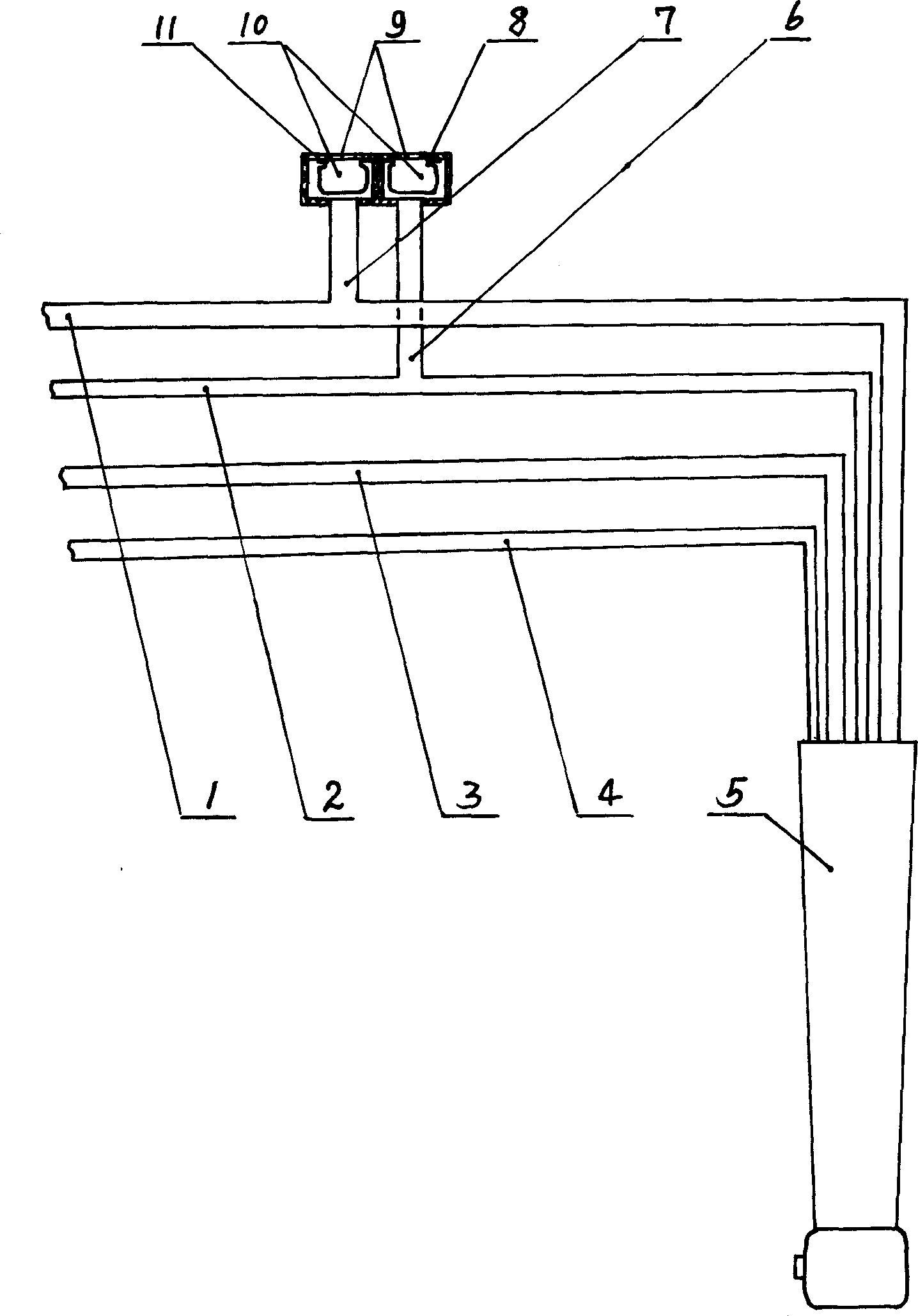
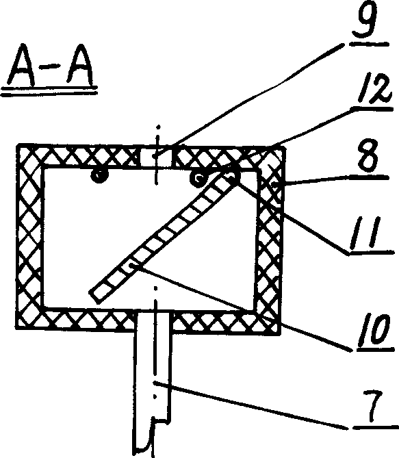
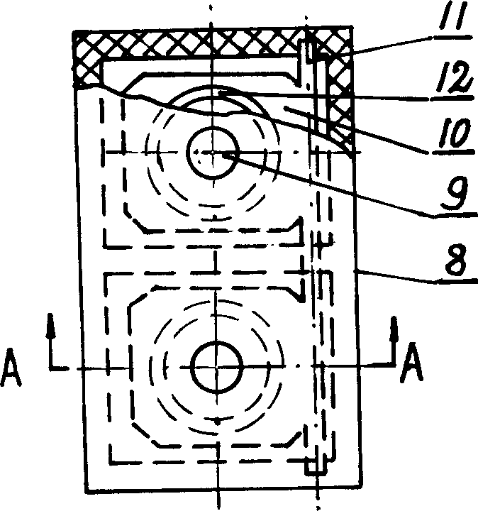
[0013] as attached Figure 1-3 As shown, take the existing Class I Type B AM8900 "chair-mounted dental treatment equipment" as an example. Self-made two interlocking check valve devices, wherein the check valve body (8) is made of plastic, and is basically composed of two mutually isolated chambers. The upper part of each chamber interlocking shaft chamber has a vent (9), and the lower part has an air vent (9). The side branch (6) of the cooling water flow pipe and the side branch (7) of the driving air flow pipe, the two movable valves (10) and the linkage rotating shaft (11) of the movable valve are the same material, preferably stainless steel, and the two are rigidly connected as One body, two pieces of movable valves are in the same plane, and the linkage rotating shaft is installed in the chamber of the check valve body to rotate. In order to ensure watertight and air leakage, a circle of gasket (12) is set around the air vent.

[0014] The side branch of the cooling w...


PUM


Abstract

The vessel resporption preventing device for dental unit includes two synchronous non-return valves connected separately to the driving airflow pipe and cooling water flow pipe in the hand set of the dental unit. Each of the valves has one end communicated with atmosphere and the other end connected with the driving airflow pipe and cooling water flow pipe. When the hand set is in operation, two valves are closed; and when the driving airflow and cooling water flow is shut off, the turbine rotates inertially to open the valves for air to be led in, so as to avoid the formation of negative pressure in the driving airflow pipe and cooling water flow pipe and to avoid resporption pollution.

Description

technical field [0001] The invention belongs to an anti-back-suction device for the cavity of a dental comprehensive treatment table. Background technique [0002] Dental high-speed turbine handpieces, hereinafter referred to as dental handpieces, are connected to the rear end with a water-transporting air pipeline consisting of a driving airflow pipe, a cooling water flow pipe, a return air pipe, and a cooling air pipe. When the dental handpiece is drilling teeth, the high-pressure driving airflow drives the turbine to rotate at a high speed of 300,000 revolutions per minute; the turbine and the bearing are cooled by the cooling water flow, and the pressure in the driving airflow pipe is at 0.12MPa to 0.18MPa. When the driving air flow and cooling water flow are cut off, the turbine will continue to rotate for a period of time due to inertia, and will draw out the air and water in the drive air and cooling water flow pipes at the back end of the dental handpiece, and form a...

Claims


Application Information

Patent Timeline
Patent Type & Authority Applications(China)
IPC IPC(8): A61C1/08
Inventor 刘帆
Owner 刘帆
Learn More