Methods of treating deposition process components to form particle traps, and deposition process components having particle traps thereon

A particle capture and particle technology, applied in cleaning methods and utensils, chemical instruments and methods, manufacturing tools, etc., can solve problems such as performance degradation and weak adhesion in particle capture areas

Inactive Publication Date: 2006-10-18
HONEYWELL INT INC
View PDF0 Cites 7 Cited by
  • Summary
  • Abstract
  • Description
  • Claims
  • Application Information

AI Technical Summary

Problems solved by technology

The bead blasted surface can have relatively poor adhesion to redeposited material entering the particle trapping area and thus can degrade the performance of the particle trapping area

Method used


Image

  • Methods of treating deposition process components to form particle traps, and deposition process components having particle traps thereon
  • Methods of treating deposition process components to form particle traps, and deposition process components having particle traps thereon
  • Methods of treating deposition process components to form particle traps, and deposition process components having particle traps thereon

Examples


Embodiment Construction

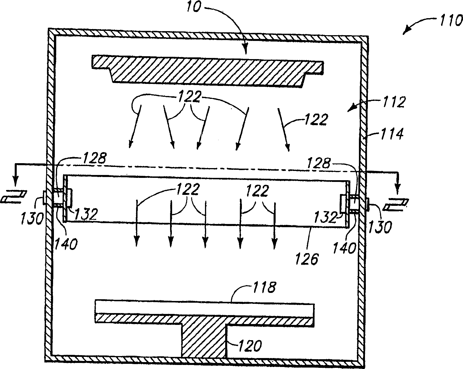
[0032] The present invention includes particle trapping regions that may be formed on one or more surfaces of physical vapor deposition components, and methods of forming the particle trapping regions. The particle trapping region can be used to trap material deposited on the part during the deposition process.

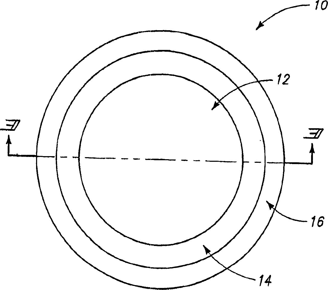
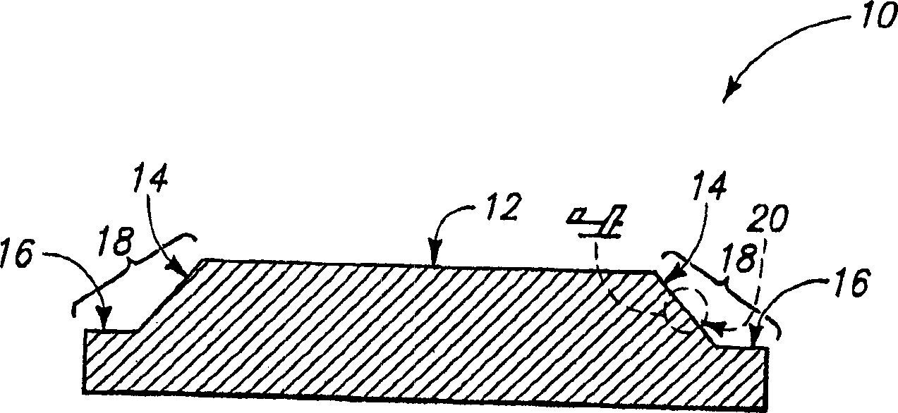
[0033] The particle trapping region is formed by bead blasting, and in some aspects machining, one or more surfaces of the physical vapor deposition component. If the processing component is a sputtering target, the processing surface may include various non-sputtering surfaces, such as sidewall surfaces, flange surfaces, and / or non-sputtering surfaces along the sputtering plane.

[0034] Protrusions formed by machining may be considered to correspond to macro-scale roughness, and roughening by bead blasting may be considered to correspond to micro-scale roughness. Thus, the present invention may include patterns having one or both of macroscale and microscale roughn...


PUM


Abstract

The present invention includes a method for forming a particle trap along a surface of a physical vapor deposition component, and includes a physical vapor deposition component having the particle trap thereon. The present invention may involve the use of highly soluble media for bead blasting and/or may involve the use of metallic materials as bead blasting media. The invention may also include forming an insert along an area of ​​the target seat where a particle trap is desired, the insert having a composition superior to the target seat in terms of particle trapping properties.

Description

[0001] Related application information [0002] This application claims priority to US Provisional Application 60 / 502,689, filed September 11, 2003; and also claims priority to US Provisional Application 60 / 543,457, filed February 9, 2004. technical field [0003] The present invention relates to a method of forming a particle trap along a region of a physical vapor deposition (PVD) process component, such as a sputtering target. Background technique [0004] Physical vapor deposition methods are used to form films of materials on the surface of a substrate. Physical vapor deposition methods are used, for example, in semiconductor fabrication processes to form layers that are ultimately used to fabricate integrated circuit structures and devices. [0005] The physical vapor deposition operation is described in conjunction with the sputtering apparatus 110 in FIG. 1 . Apparatus 110 is an example of an ionic metal plasma (IMP) apparatus and includes a chamber 112 having side...

Claims


Application Information

Patent Timeline
Patent Type & Authority Applications(China)
IPC IPC(8): C23C14/56B08B7/00C23C14/34C23C16/44
CPCB24C1/00B24C11/00C23C14/3407C23C14/564C23C16/4404B08B7/00C23C14/34C23C14/56C23C16/44
Inventor 金在衍S·R·赛尔斯J·K·卡多库斯T·J·费兰
Owner HONEYWELL INT INC
Why Eureka
Try Eureka