Method and circuit arrangement for the detection of ground faults on electronic trips for low-voltage circuit breakers comprising serially connected measuring amplifiers

A technology for measuring amplifiers and power switches, applied in the direction of measuring electricity, measuring devices, circuit devices, etc., can solve the problems of not being able to form phase currents accurately enough, and achieve the effect of easily determining the magnification and eliminating inaccuracy

Inactive Publication Date: 2006-10-18
SIEMENS AG
View PDF1 Cites 0 Cited by
  • Summary
  • Abstract
  • Description
  • Claims
  • Application Information

AI Technical Summary

Problems solved by technology

However, large errors can occur here, since the small ground current that results in discharge corresponds to only about two conversion st

Method used


Image

  • Method and circuit arrangement for the detection of ground faults on electronic trips for low-voltage circuit breakers comprising serially connected measuring amplifiers
  • Method and circuit arrangement for the detection of ground faults on electronic trips for low-voltage circuit breakers comprising serially connected measuring amplifiers

Examples


Embodiment Construction

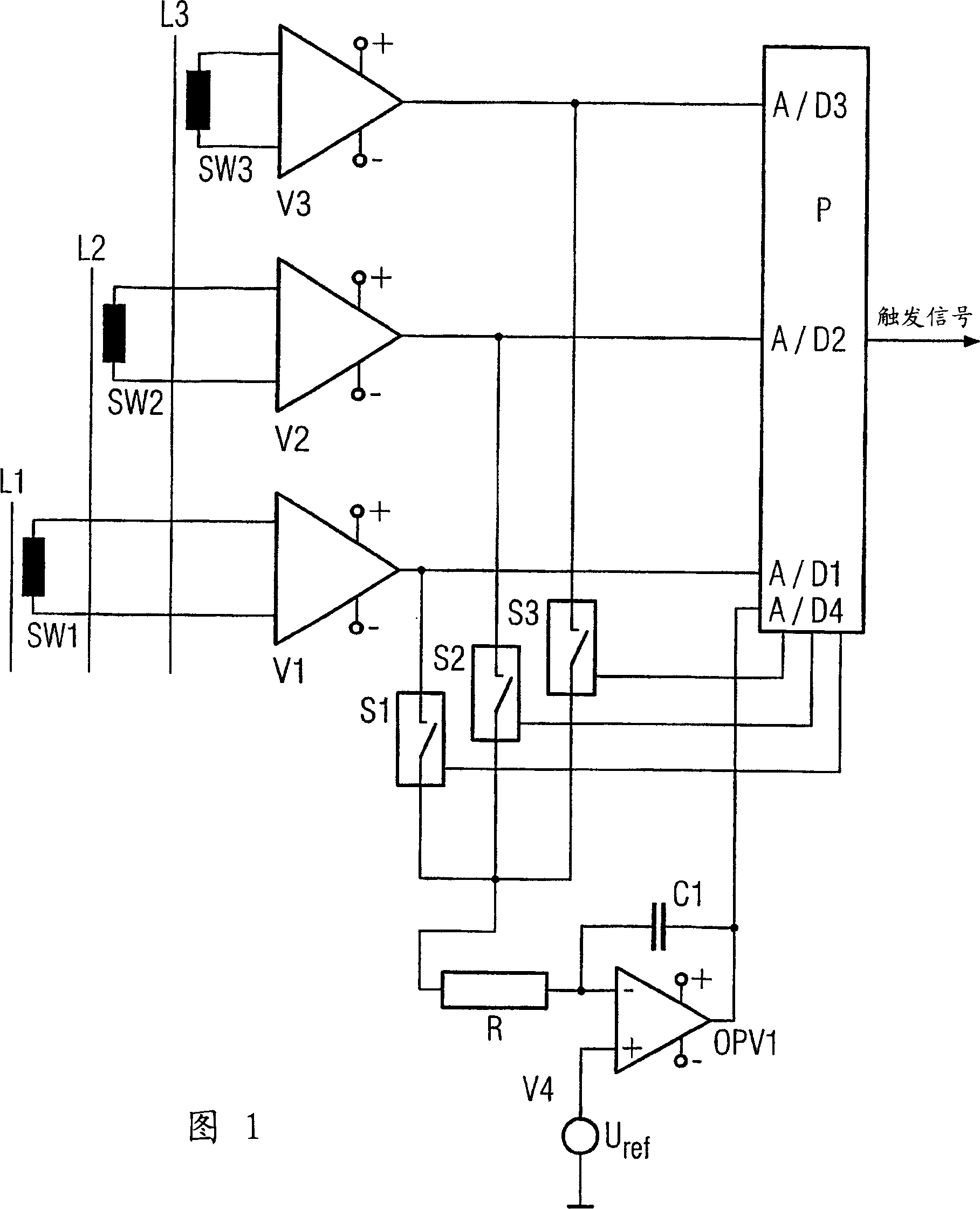
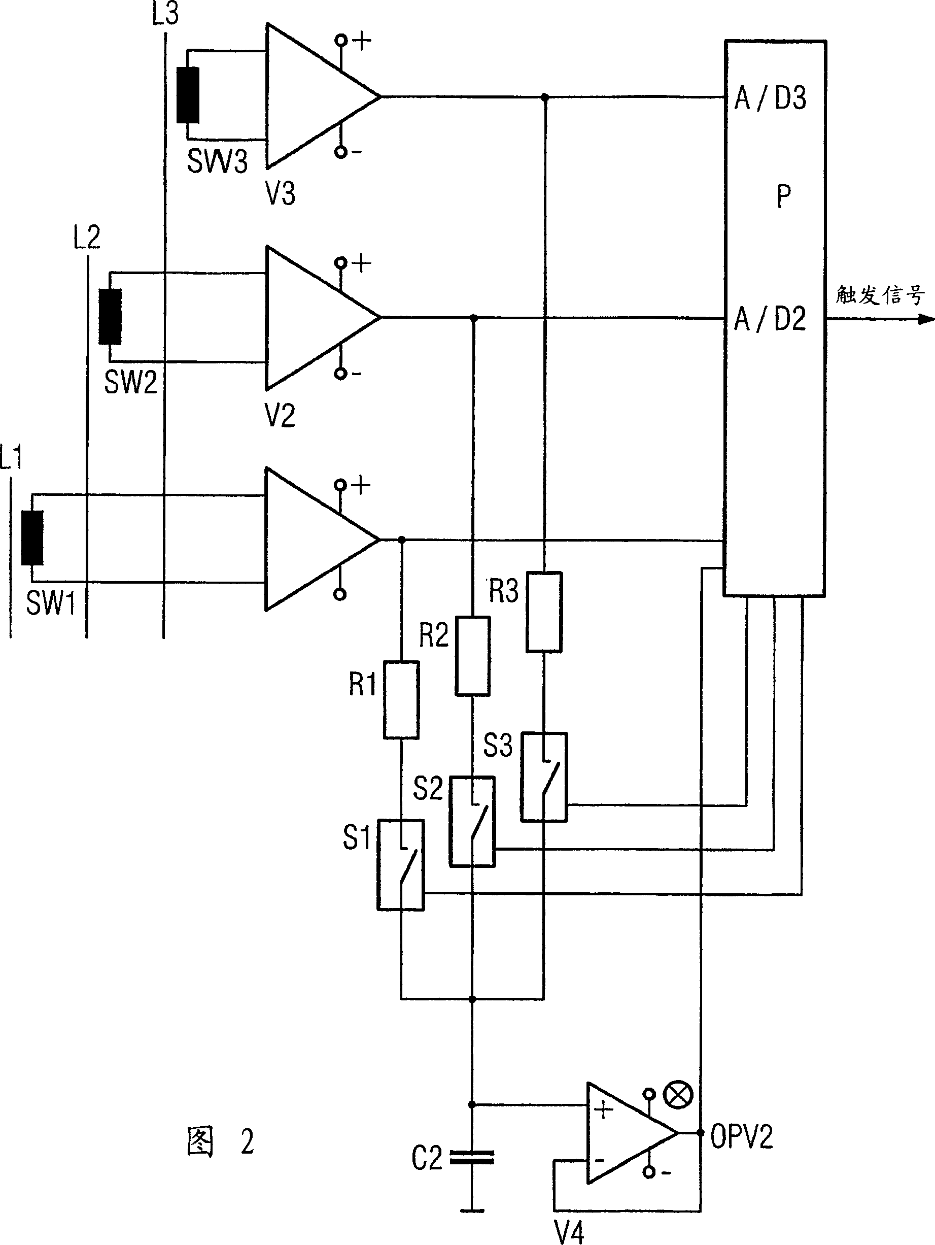
[0013] Figure 1 schematically shows an electric release on a three-phase grid. The currents flowing through the converters SW1, SW2, SW3 are measured on the three conductors L1, L2, and L3 of the grid, and are directed to the measuring amplifiers V1, V2, V3. The output of these measuring amplifiers is directed to the microprocessor μP A / D converter A / D1, A / D2, A / D3, the microprocessor is an important functional part of the release.

[0014] According to the present invention, the output signals of the measuring amplifiers V1, V2, V3 are introduced into the switches S1, S2, S3 controlled by the microprocessor μP in a pulse width modulation manner. The switches S1, S2, S3, which are only schematically shown here, can be realized by switching transistors, for example. If one switch S1, S2, S3 is current-on, the other switches are off, and the pulse duty factor corresponds to the amplification factor of the respective measuring amplifiers V1, V2, V3. The output of the switches S1, S2,...


PUM


Abstract

The problem with ground acquisition is that the measurement amplifier has a large tolerance in terms of its magnification. There are thus large errors in error handling in software. It is therefore advisable to sum the output signals of the measuring amplifiers in a phase-wise, pulse-modulated manner in a summing amplifier, wherein the duration of the pulses is controlled via releasers depending on the amplification factor of the individual measuring amplifiers, and the output of the summing amplifiers is used as Signal for monitoring ground.

Description

Technical field [0001] The invention relates to a method and a circuit arrangement, which are used for collecting the grounding on the electric release of a low-voltage power amplifier by using a pre-measurement amplifier. Background technique [0002] The low-voltage power switch has other functions besides its main function, that is, short-circuit monitoring and over-current monitoring. The most important function is grounding monitoring. Grounding can produce unmanageable results in electrical equipment by, for example, triggering sparks. Therefore, a power switch with a corresponding ground recognition function is used to delay the elimination of the spark by turning off the power switch, or at least to inform that the spark has occurred. For this reason, for two-pole or bipolar power switches, the vector sum of the phase current and the current is formed in the N-conductor, if there is an N-conductor converter. If the residual current exceeds the start value, display it and ...

Claims


Application Information

Patent Timeline
IPC IPC(8): H02H3/16G01R31/02H02H3/00
CPCG01R31/52H02H3/006H02H3/16
Inventor 安德烈亚斯·潘克伊尔卡·雷德曼沃尔夫冈·罗尔
Owner SIEMENS AG
Why Eureka
Try Eureka