

Wet-type cleaner capable of changing power
A cleaning device and power technology, applied in cleaning equipment, cleaning machinery, carpet cleaning, etc., can solve the problems of time-consuming, inconvenient users, large volume, etc., and achieve the effect of good suction efficiency
- Summary
- Abstract
- Description
- Claims
- Application Information
AI Technical Summary
Problems solved by technology
Method used
Image

Examples
Embodiment 1
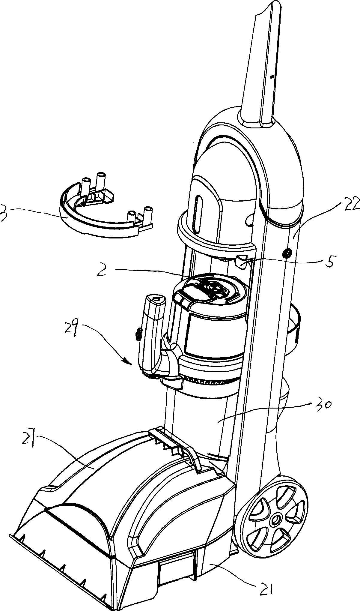
[0023] as attached figure 1 , attached figure 2 As shown in accompanying drawing 8, a kind of variable power wet cleaning device comprises a base 21 adapted to move on the surface to be cleaned; an upright handle 22 pivotally connected to the base 21; at least partly arranged on the a liquid dispensing system 23 on one of the base 21 or upright handle 22; a vacuum source including a motor 20 and a fan connected to the motor 20; and a liquid recovery system 19.
[0024] The liquid dispensing system 23 further comprises: a liquid dispensing head 25 for spraying the liquid onto the surface to be cleaned; a liquid supply tank 24 for containing the cleaning liquid; and a liquid supply tube for supplying the liquid to the liquid dispensing head 25 26 ; the liquid supply barrel 24 is arranged on one side of the upright handle 22 , and the liquid supply barrel 24 communicates with the liquid distribution head 25 through the liquid supply pipe 26 .
[0025] The liquid recovery syste...
Embodiment 2
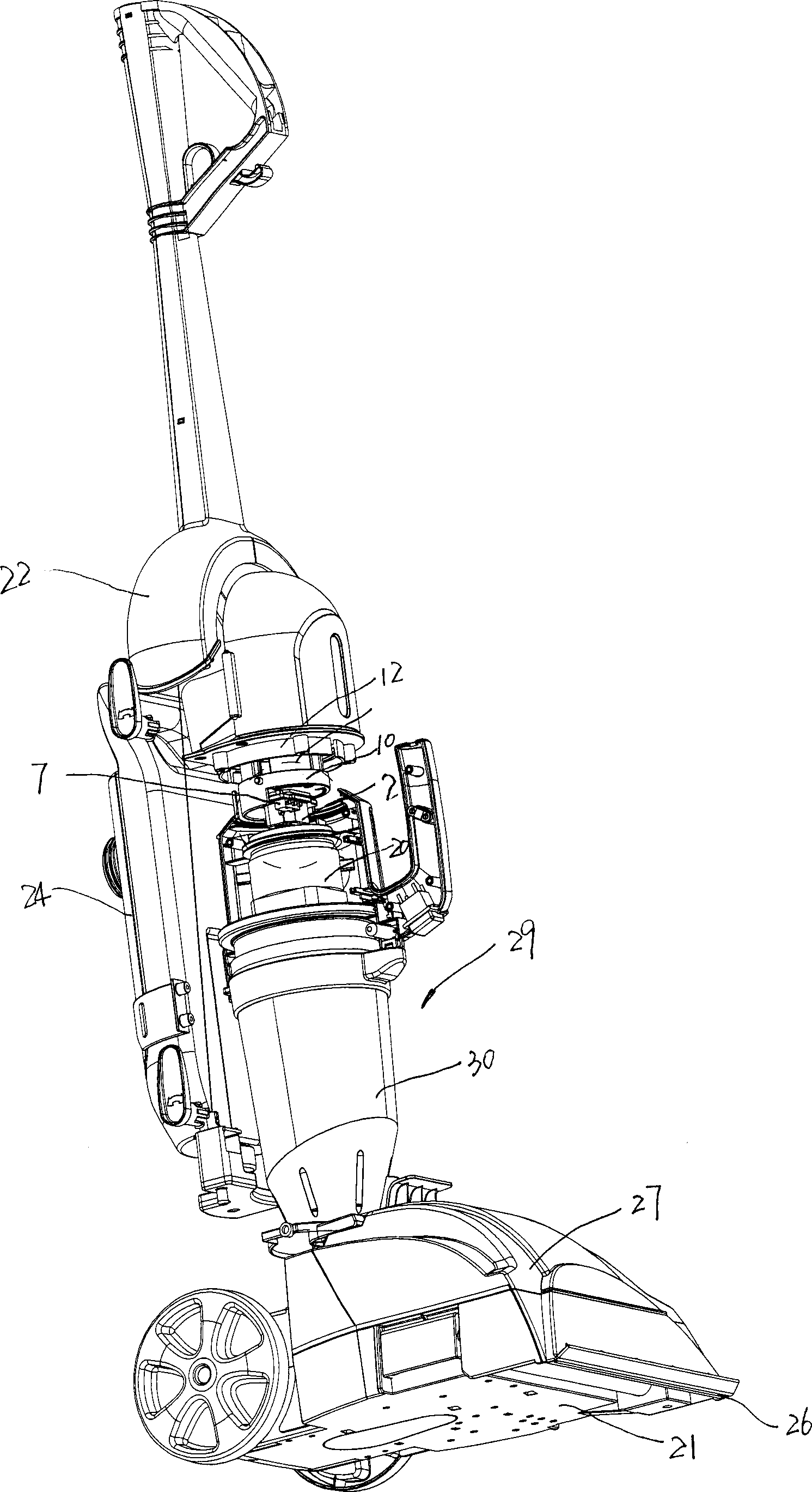
[0031] as attached figure 2 to attach Figure 5 As shown, the variable power wet cleaning device also includes a plug socket 33, and the plug socket 33 includes a plug 1 that is arranged on one of the two parts of the portable mechanism 29 or the upright handle 22 and is arranged on the The socket 2 on the other part of the two parts of the portable mechanism 29 or the upright handle 22 is in the first working position between the portable mechanism 29 and the upright handle 22, and the The plug 1 is electrically connected to the socket 2; when the portable mechanism 29 and the upright handle 22 are in the second working position, the plug 1 is electrically connected to the socket 2 separate.
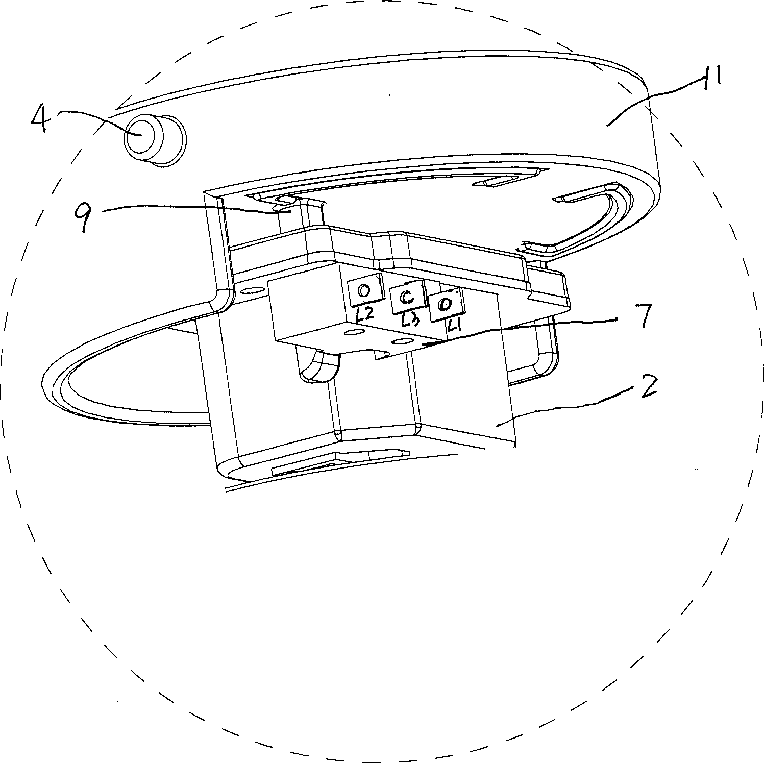
[0032] The plug 1 is fixed on the plug connection part 11 , and the control rod 9 is also fixedly arranged on the plug connection part 11 . The plug stopper 6 is fixedly arranged on the upright handle 22 , and the plug connection part 11 is slidably arranged on the plug stopper 6 . ...
Embodiment 3
[0038] as attached Figure 6 And attached Figure 7 As shown, wherein M is the motor 20, and K is an ordinary switch. The PCB is an ordinary step-down chip, which can reduce the effective value of the alternating voltage. Because it is a commonly used product, it is easy to buy in the market, so its internal components and circuits will not be described again.
[0039] The travel switch 7 is a travel switch, which has three contacts L1, L2, L3, wherein L1 is electrically connected to the high-power input circuit, that is, L1 is connected to the zero line of the socket 2. L2 is electrically connected to the low-power input circuit, that is, L2 is connected to the neutral line of socket 2 through the step-down chip PCB. L3 is connected to the fire wire of socket 2 through motor 20 . When the portable mechanism is assembled on the upright handle and connected with the upright handle as a whole for combined operation, toggle the lever 5 to make the plug 1 stretch out to the soc...
PUM
 Abstract
Description
Claims
Application Information